What is Flyback Converter?
A flyback converter is a power converter that can be used for ac to dc conversion and dc to dc conversion while isolating the input and output sides. In other words, a flyback converter can produce a regulated dc output from an ac or dc input. This type of converter uses a special type of electrical transformer called flyback transformer which is basically a mutually coupled inductor.
In this article let us see about a dc to dc flyback converter. A dc to dc flyback converter is a buck-boost converter where it can produce an output dc voltage that is either greater or lesser than the input dc voltage.
Circuit Diagram of Flyback Converter :
A flyback converter uses a special device called Coupled Inductor. A coupled inductor contains two or more windings on the same core similar to a transformer. We know that a transformer is used to transfer power from one winding to another winding. Whereas a coupled inductor is a split inductor that stores a significant amount of energy in the core flux.
The coupled inductors can efficiently provide required output voltages which can either be stepped up or stepped down with the additional advantage of isolation between the input and output. A coupled inductor often would regard as a special type of transformer.
The below shows the circuit diagram of a flyback converter which is similar to a buck-boost converter. The input dc source is connected across the primary coil (LP) of the coupled inductor through a power semiconductor switch (transistor or thyristor) which is controlled by PWM signals. The output of the flyback converter is taken from the secondary coil (LS).
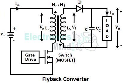
The relative polarity of the coupled inductor is represented by dot convention. It can be seen that, if current enters at the dotted terminal of the primary coil, the secondary coil’s positive polarity will be at the opposite side. A diode is connected in series with the secondary coil which also acts as the switch allowing current only in one direction. A capacitor is used across the output to reduce ripple voltage.
Working of Flyback Converter :
The operation of a flyback converter is very similar to a buck-boost converter where a chopped output voltage is obtained by controlling the semiconductor switch (here a power MOSFET is used as a switch).
When the MOSFET is made to conduct by applying a signal at its gate terminal. The dc voltage source gets connected across the primary coil of the coupled inductor and the source current starts flowing through the primary coil as shown below.
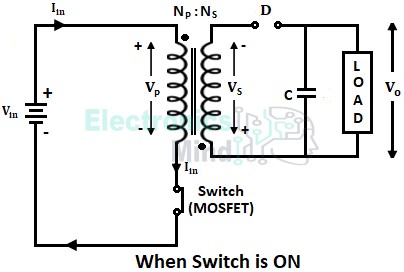
During the turn-ON period of MOSFET, the current flowing through the primary coil increases gradually storing energy in the inductor core. Since the current enters into the primary coil through the dotted terminal. The voltage polarity of the secondary coil will be inverted i.e., the dotted terminal of the secondary become positive and the other terminal will be negative (as per dot convention).
We can see that a negative voltage is applied across the diode, resulting in a reverse bias of the diode. Thus when the MOSFET is ON, the diode acts as the open switch, and no current flows in the secondary coil.
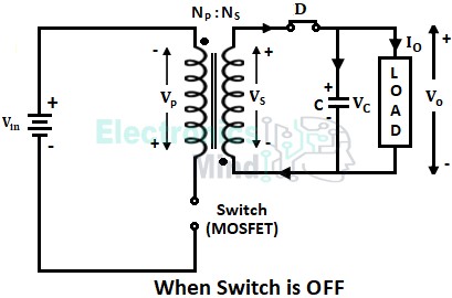
Now when the MOSFET is turned OFF, the primary coil is disconnected from the dc voltage source due to which there will be a sudden drop in current flowing through the primary coil. Simultaneously, the inductor will doesn’t allow this sudden change in current and it induces a voltage with reverse polarity i.e., the dotted terminals will become negative.
This results in a positive voltage across the diode, due to which the diode will forward bias and acts as a closed switch. Thus the stored energy in the inductor core starts flowing through the diode and the energy from the secondary coil is transferred to the load and charges the capacitor as shown below.
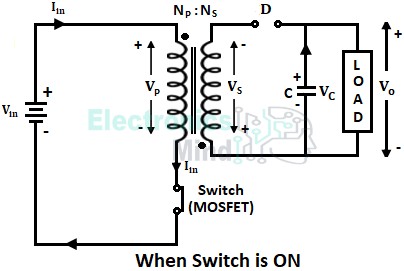
Again when the MOSFET is turned ON, the coupled inductor is charged again. At this time the charged capacitor across the output will supply energy to the load as shown below.
In this way, the MOSFET is turned ON and OFF at regular intervals of the period to obtain a chopped output. Therefore we can conclude that,
- When the MOSFET is in the ON state, the coupled inductor will store energy in it and the capacitor will supply energy to the load.
- When the MOSFET is in the OFF state, the coupled inductor will supply energy to the load and the capacitor will be charged.
The below shows the waveforms for the above flyback converter operation.
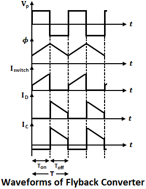
In the above waveforms, TON represents the MOSFET ON-state period and TOFF represents the MOSFET OFF-state period. During the TON period of the MOSFET, the primary coil voltage VP will be equal to the input voltage Vin and energy is stored in the core magnetic field Φ generated by the current Iin. Since the diode is reverse biased during the MOSFET ON period, ID will be zero.
Now during the TOFF period of the MOSFET, current Iswitch through MOSFET becomes zero and stored energy Φ in the inductor is released through the diode ID. Since inductor polarity changes when the MOSFET is turned OFF, VP and VS are reversed.
Advantages of Flyback Converter :
- Since there is no direct electrical connection between input and output, a flyback converter provides good isolation.
- From a coupled inductor there can be more than one output by placing multiple secondary coils with a single primary coil. Thus we can obtain multiple outputs from a single input using a flyback converter.
- By changing the winding ratio we can operate a flyback converter as a buck converter (where the output voltage is less than the input voltage) or boost converter (where the output voltage is more than the input voltage).
Disadvantages of Flyback Converter :
- This type of converter configuration has discontinuous input and output currents which results in ripple.
- High RMS and peak currents in the design.
Good explanation.