The current commutated chopper is a type of forced commutated chopper that uses an oscillatory current in order to turn OFF the main thyristor. The oscillatory current flowing through the chopper must be greater than the load current.
Similar to the capacitor in a voltage commutated chopper, the oscillatory current to commutate the main thyristor in this chopper is obtained from a charged capacitor. This type of chopper circuit is also known as Resonant-Pulse Commutated Chopper. Let us see the circuit diagram, working and related waveforms of the current commutated chopper.
Circuit of Current Commutated Chopper :
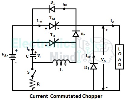
The below shows the circuit configuration of the current commutated chopper. It consists of main thyristor TM and auxiliary thyristor TA. The components inductor (L), capacitor (C), TA, diodes (D1 and D2) forms the commutating circuit in order to turn OFF the main thyristor.
In the above chopper circuit,- The load current IO is assumed to be constant.
- The internal resistance of thyristors and diodes is assumed to be zero.
- The resistor is assumed to be so large that during commutation of the thyristor, it remains as an open circuit.
Working of Current Commutated Chopper :
For convenience, the working of the current commutated chopper can be explained in five modes. Before initiating the operation, the capacitor in the circuit must be charged to the source voltage. This can be done by closing the switch (S) and the charging current flows through the path Vdc+ → C → S → R → Vdc–. The charge that is stored in the capacitor is used for the commutation process.
Once the capacitor is charged, the switch is opened and the main thyristor TM is triggered at instant t = to. Once TM starts conducting, load voltage VO follows source voltage Vdc, whereas, load current IO remains constant.
Mode I (t1 < t < t2) :
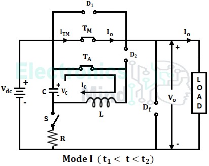
Mode I starts when the auxiliary thyristor TA is triggered which is at instant t = t1, and the commutation process starts at this instant. Now, an oscillatory current IC of magnitude (Vdc sin ωot)/ωoL is set up in the circuit and it flows through the path C+ → TA → L → C– as shown below.
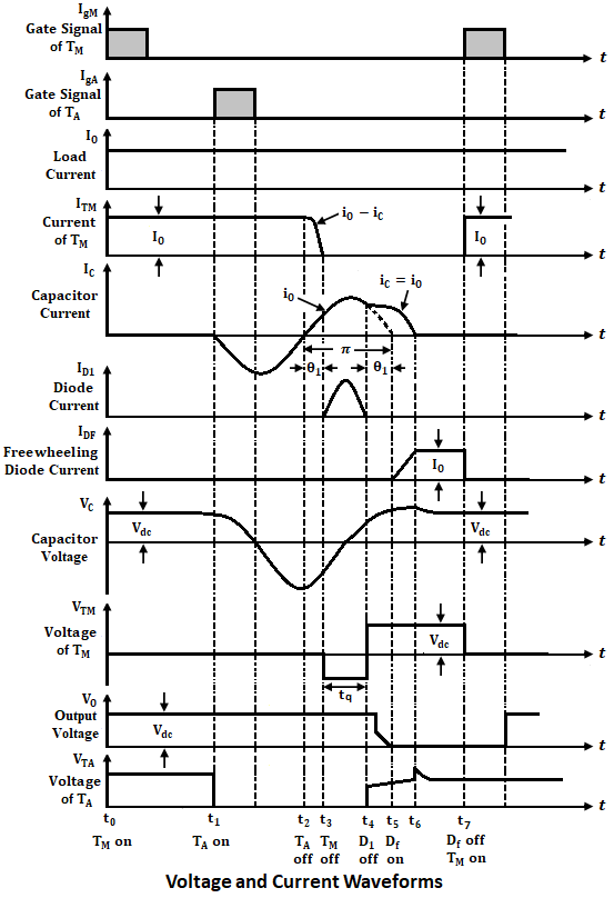
This oscillatory current increases as a function of sine and reaches its negative maximum value and finally becomes zero at instant t2. Now, at instant t2 capacitor voltage reverses completely i.e., VC = -Vdc, capacitor current IC changes its direction of flow in the auxiliary thyristor TA due to which TA is reverse biased and turned OFF.
Also in this mode, from t1 to t2 main thyristor TM is neither triggered nor commutated. So, load current and load voltage remain as IO and Vdc only. At t = t2, the upper plate of the capacitor becomes negative and the lower plate to positive.
Mode II (t2 < t < t3) :
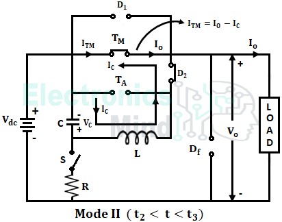
As soon as the auxiliary thyristor TA gets turned OFF at t2, oscillatory current IC flows through the path C+ → L → D2 → TM → C– as shown below.
Here, IC flows through TM since it is still in a conduction state. As TM is ON, the ON-stage voltage drop of TM appears across D1 and it is reverse-biased, thereby not allowing to flow IC through it. The net current flowing through thyristor TM will be (IO – IC), since load current IO is flowing in the opposite direction to that of IC.
At instant t = t3, IC increases and reaches IO due to which the current flowing through main thyristor TM becomes zero (i.e., ITM = IC – IL = 0) and hence it is commutated.
Mode III (t3 < t < t4) :
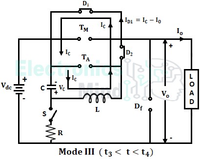
In this mode of operation, with the commutation of main thyristor TM, IC increases and reaches a value higher than load current IO as shown in waveforms below. Hence, this excess current (IC – IO) starts flowing through the diode D1 as shown below.
Due to the flow of current, there will be a drop in voltage across D1. This voltage appears across TM as reverse voltage as they are in parallel and hence keeps TM in OFF state for the time tq (shown in the waveform).
At instant t = t4, if VC > Vdc then the free-wheeling diode (DF) gets forward biased and starts conducting. However, if VC < Vdc, then the circuit operates in Mode IV.
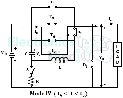
Mode IV (t4 < t < t5) :
This mode starts at instant t = t4, at which IC reduces to IO. Because of this the current flowing through the diode D1 becomes zero, and hence it is reversed biased and turned OFF. After t = t4 the load current will be constant and follows the path Vdc+ → C → L → D2 → load → Vdc– as shown below.
At instant t5 the capacitor is again charged to source voltage Vdc with upper plate positive and lower plate negative.
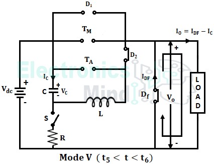
Mode V (t5 < t < t6) :
At instant t5, the capacitor charges at a higher rate, and it gets charged to a value greater than the supply voltage source. Due to overcharging of the capacitor, free-wheeling diode DF gets forward biased and starts conducting as shown below.
At this instant, since DF is conducting, load voltage VO becomes zero, and IC reaches zero at instant t6. Then after diode D2 is reverse biased and turned off. Now, the load current IO flows through the freewheeling diode DF until the main thyristor TM is triggered again. These five modes will repeat again when TM has triggered again. The below shows the voltage and current waveforms.
In the above chopper operation, we can notice that in mode II, the main thyristor is commutated by applying a reverse current pulse generated by the capacitor. Hence the chopper circuit is called as Current Commutated Chopper. This type of chopper circuit is widely used in traction cars.

