A chopper is basically a power semiconductor device used to obtain a desired dc voltage from an unregulated dc voltage source. The chopper circuit employs a thyristor that is turned ON and turned OFF at the required instant to get desired output. But the most undesirable feature of the thyristor is it cannot turn OFF by itself.
Thus, in order to turn OFF or commutate thyristor, there are some commutation circuits that are broadly classified into two groups,
- Load Commutation and,
- Forced Commutation.
Load Commutation :
In load commutation, the thyristor is turned OFF by reducing the current flowing through it to zero. This can be achieved either by load circuit parameters that bring thyristor current to zero or by diverting current flow away from the thyristor path.
Forced Commutation :
In this technique, energy storage elements such as inductor and capacitor are connected additionally in the circuit. Using these external elements the forced commutation can be achieved in two ways,
- Voltage Commutation – In voltage commutation, a reverse voltage is applied across the thyristor using a charged capacitor. So that conducting thyristor reverse-biases and turned OFF.
- Current Commutation – In current commutation, a current pulse greater than the load current is applied to the thyristor in the reverse direction. Due to this reverse current, both load and reverse currents cancel each other, and thus the net current flowing through the thyristor becomes zero, thereby turning OFF the thyristor.
In this article, let us learn about circuit construction and working of voltage commutation technique in chopper or voltage commutated chopper. This type of chopper circuit is also called impulse commutated or classical or parallel-capacitor turn OFF or oscillation chopper.
Circuit of Voltage Commutated Chopper :
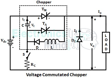
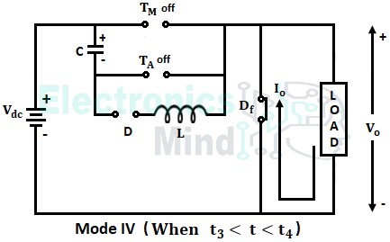
The below shows the circuit diagram of voltage commutated chopper. It consists of a main thyristor TM and auxiliary circuit that compresses components inductor (L), capacitor (C), auxiliary thyristor (TA), diode (D) for commutating the main thyristor TM.
A freewheeling diode Df is connected across the load to freewheel the current due to load inductance. In the above circuit load current IO is assumed to be constant, and zero losses in thyristors and diodes.
Working of Voltage Commutated Chopper :
To simplify the understanding of the operation of voltage commutated chopper, the entire operation is divided into four different modes. Before starting the chopper circuit, the capacitor C must be charged to positive source voltage Vdc with the upper plate as positive polarity and lower plate as negative polarity as shown in the above circuit.
The charging of capacitor can be done in either of the following two ways,
- To connect extra circuit that compresses of a switch (S) and resistance (RC) as shown above. The switch (S) is closed until the capacitor gets charged to the source voltage through the path Vdc+ → C → S → RC → Vdc–. Once the capacitor voltage becomes equal to source voltage i.e., VC = Vdc, the switch is opened and is remained open during the entire operation of the chopper.
- Another way of charging the capacitor is by triggering auxiliary thyristor TA so that capacitor gets charged to Vdc through the path Vdc+ → C → TA → load → Vdc–. Once the charging current becomes zero, TA is turned OFF and thus VC will become equal to Vdc.
Now let us see the operation of the chopper in different modes.
Mode I :
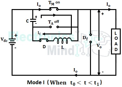
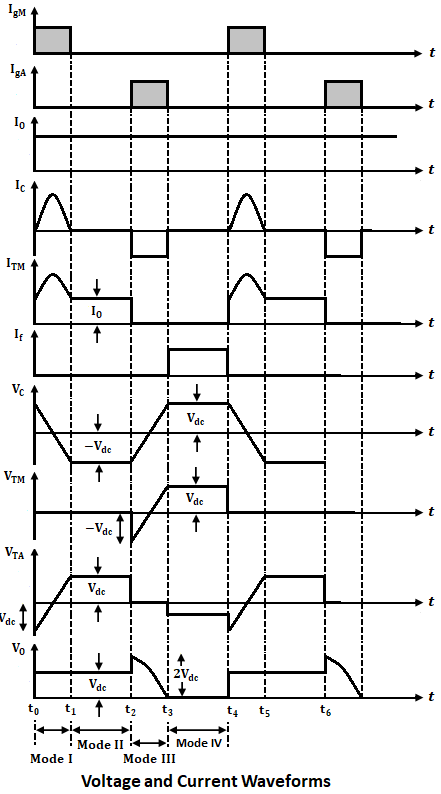
In this mode of operation, the main thyristor TM is triggered at an instant of time t0, and thus the load is connected to the source. Now load voltage VO follows source voltage Vdc.
Once TM starts conducting the current in the circuit flows through two paths. The load or output current IO constitutes one path that flows through the path Vdc+ → TM → load → Vdc–, and commutation current IC constitutes another path that flows through C+ → TM → L → D → C– as shown below.
Now after a while capacitor voltage, VC reaches zero from its initial value, whereas, capacitor current IC reaches its maximum value. Now, IC decreases from its maximum value and becomes zero at instant t1, and the capacitor starts charging in the opposite direction to -Vdc. This reverse voltage -Vdc in the capacitor which is varying as a function of cosine is held constant (at -Vdc) by diode D.
This mode ends at an instant t1 and the state of the circuit at the end of mode will be,
Mode II :
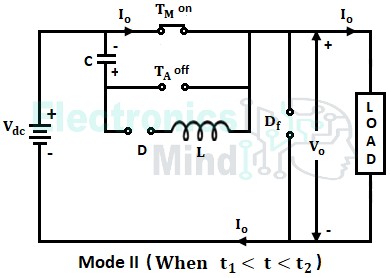
In this mode of operation, the main thyristor will remain in the conduction state and the auxiliary thyristor will be in a nonconduction state. Since there is no change in the circuit, the load current flows through the main thyristor similar to the path in mode I as shown below. This condition continues until t2, till then the circuit state will remain the same as that of mode I.
Mode III :
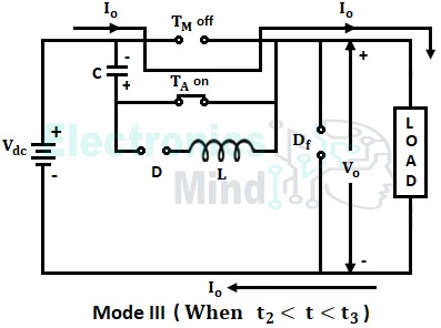
This mode starts at desired instant t2 when auxiliary thyristor TA is triggered. As TA is triggered, it starts conducting and the capacitor voltage to which it is charged i.e., -Vdc, appears across the main thyristor TM.
Thus main thyristor TM becomes reverse-biased due to reverse voltage and it gets turned OFF. Hence load current flowing through thyristor TM becomes zero at t2 and now the load current flows through the auxiliary thyristor TA in the path Vdc+ → C → TA → load → Vdc– as shown below.
The load voltage VO at instant t2 is given by the sum of source voltage Vdc and the voltage across the capacitor VC i.e., VO = Vdc + Vdc = 2Vdc. Now, the load voltage decreases from 2Vdc to Vdc at a certain instant of time, and finally, the load voltage becomes zero at t3.
As VO decreases, the voltage across the capacitor also decreases. Then after VC charges linearly from -Vdc at t2 to Vdc at t3 since load current is assumed to be constant. At the end of this mode, the circuit state will be,
Mode IV :
This mode is from instant t3 where VC = VTA = Vdc, VO = 0, and capacitor current becomes zero. Thus auxiliary thyristor TA is turned off naturally and capacitor C is charged to a higher value at t3.
Due to slight overcharging of the capacitor, the freewheeling diode Df is forward biased and it conducts. As a result, the load current IO flows through the load and freewheeling diode as shown above. From t3 to t4, the voltage through the auxiliary thyristor becomes slightly negative since the capacitor is overcharged at t3. In this mode, the state of the circuit will be,
The below shows the related voltage and current waveforms for voltage commutated chopper.
At instant t4 main thyristor is triggered again and the process described from t0 to t4 repeats again. Since the main thyristor is commutated by impressing a reverse voltage obtained from the charged capacitor, the circuit is said to be called Voltage Commutated Chopper.

