A diode rectifier or uncontrolled rectifier is the converter circuit that converts ac signal into (an alternating signal) dc signal (unidirectional signal). Uncontrolled rectifier circuits use diodes to convert ac power to dc power and are divided into two types, single-phase and three-phase. Again singe-phase uncontrolled rectifiers are divided into two types, they are,
- Half-wave uncontrolled rectifier
- Full-wave uncontrolled rectifier
- Center tapped rectifier
- Bridge rectifier
In a single-phase half-wave uncontrolled rectifier circuit only either the positive or negative half-cycle of the ac input is converted into dc. Whereas a single-phase full-wave uncontrolled rectifier converts both the positive or negative half-cycle of the ac input into dc.
In full-wave rectifiers, there are two types of circuit configurations, center-tapped, and bridge-type full-wave rectifiers. A center-tapped rectifier uses a center-tapped transformer and two diodes whereas a bridge rectifier uses four bridges.
The performance of both center-tapped and bridge rectifiers is almost identical, except the bridge configuration has the advantages of reduced peak inverse voltage across diodes and improved transformer utilization factor. In this article let us see the circuit diagram and operation of a single-phase full-wave bridge rectifier.
Single Phase Full Wave Bridge Rectifier with R-Load :
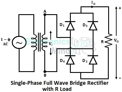
The below figure presents the circuit connection of a single-phase full-wave bridge rectifier loaded with a resistive load. A full-wave bridge rectifier uses four diodes connected in a close-loop configuration which converts alternating current into direct current. The ac input to the uncontrolled full wave rectifier is given through a transformer.
When the ac supply source to the rectifier is turned ON, the positive half cycle of ac input starts. During the positive half cycle of ac input, point A in the above circuit is made positive with respect to point B. Due to this, diodes D1 and D2 are forward biased (since their anode terminals are connected to positive with respect to the cathode), and diodes D3 and D4 are reverse biased (since their anode terminals are connected to negative with respect to the cathode).
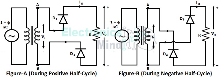
Thus diodes D1 and D2 act as the closed switch and diodes D3 and D4 act as the open switch. Therefore, the current starts flowing from point A, through diode D1, the load resistance R, and diode D2 to point B as shown below in figure A. The load current will continue to flow through D1 and D2 until the positive half-cycle ends.
Once the positive half cycle of ac input ends, the negative half cycle starts where the positive and negative terminals of the supply source are reversed. During the negative half cycle, point B is made positive with respect to point A. Due to this, diodes D1 and D2 are reverse-biased, and diodes D3 and D4 are forward-biased.
Thus, during the negative half-cycle conduction takes place from point B, through diode D3, the load resistance R, and diode D4, to point A as shown above in figure B. The load current will continue to flow through D3 and D4 until the next positive half-cycle starts.
Therefore, two diodes will always be in conduction providing a path for the current to flow in an alternating direction through the supply, but in the same direction through the load, and thus the output voltage developed across the load will be in the same direction throughout the whole input cycle.
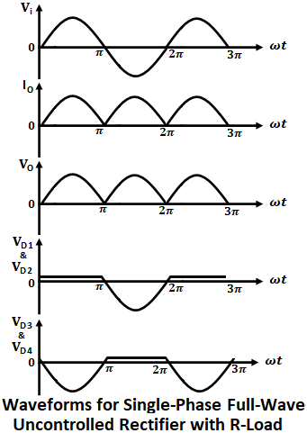
Hence a dc voltage will appear across the load from an ac source. The below shows the waveforms for output voltage Vo, output current Io, and the voltage drop across diodes.
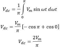
Since the load is of resistive type, the load current will be in phase with the load voltage i.e., the load current will have the same waveform as the load voltage. During the positive half-cycle i.e., from ωt = 0 to π, diodes D1 and D2 conduct, and during the negative half-cycle i.e., from ωt = π to 2π, diodes D3 and D4 conduct. The average value of the load voltage Vdc can be calculated as follows,
It can be seen that the average output voltage of a full-wave rectifier is twice of a half-wave rectifier. The average value of the output current Idc is,
The output dc power is given by,
Single Phase Full Wave Bridge Rectifier with RL-Load:
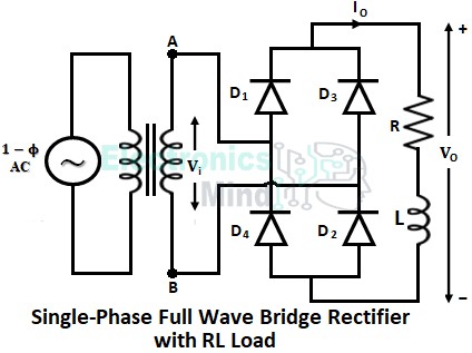
In the above circuit, we have seen the full wave bridge rectifier with a resistive load where the output current and voltage will be in phase. However, in practice loads are not purely resistive but contain inductance in combination with the resistance. Let us see the circuit operation of an uncontrolled full wave bridge rectifier with RL-load.
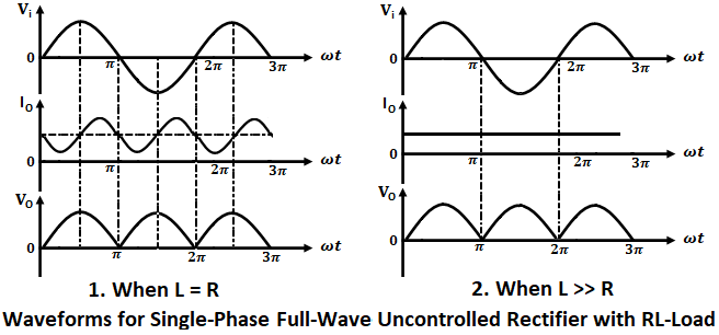
For an RL load, the average output voltage of the rectifier will be the same as in the case of resistive load, but the output current waveform changes and it becomes continuous (non-zero) depending upon the value of load inductance and load resistance. For a highly inductive load where L is much greater than R, the load current will be constant. The waveforms for output voltage and current with RL load are shown below.
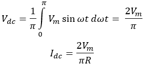
The value of average output voltage and output current with RL load is given by,
Advantages of Full Wave Bridge Rectifier:
- The efficiency of a full-wave bridge rectifier is high.
- The output dc voltage of a full-wave rectifier is almost equal to the input ac signal, whereas, in a half-wave rectifier, only half the cycle of ac input will reach the load.
- Ripple factor is less.
- High transformer utilization factor of source transformer.
- A bridge rectifier doesn’t require any center-tapped transformer.
- In a bridge rectifier peak inverse voltage of each diode is low.
- In a center-tapped full-wave rectifier only half of the transformer secondary is used at a time, whereas in a bridge rectifier entire transformer secondary is used. Thus required transformer rating in the bridge rectifier is smaller than the center-tapped rectifier.
Disadvantages of Full Wave Bridge Rectifier:
- Higher voltage drop since two diodes conducts at a time in a bridge rectifier which leads to poor voltage regulation when working with low voltages.
- In a center-tapped rectifier if one diode fails the circuit still works as a half-wave rectifier, but if one diode fails in a bridge rectifier complete circuit fails.
Since a bridge rectifier eliminates most of the drawbacks of the center-tapped rectifier and can supply a large amount of dc power to the load. It is therefore used in most power electronics applications to convert ac power into dc power.

it’s godd to read