Controlled Rectifier – Circuit, Types & Advantages
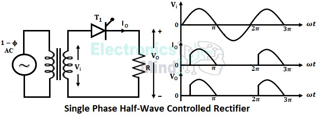
A controlled rectifier uses controllable semiconductor devices like thyristors, IGBTs, etc. We know that an uncontrolled rectifier gives a fixed dc output voltage,
Power Electronics is the branch of electrical and electronics engineering that deals in processing and controlling electrical energy required by the load.
A controlled rectifier uses controllable semiconductor devices like thyristors, IGBTs, etc. We know that an uncontrolled rectifier gives a fixed dc output voltage,
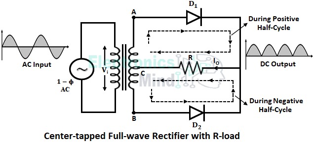
The center-tapped and bride-type rectifiers are two different types of circuit constructions that converts both positive and negative cycles of ac into dc.
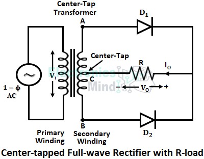
A center-tapped full-wave rectifier circuit uses a center-tapped transformer and rectifying circuit which consists of two diodes for the conversion of ac power into dc power.
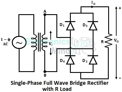
A full-wave bridge rectifier uses four diodes connected in a close-loop configuration which converts alternating current into direct current.
In a half-wave rectifier only either the positive or negative half-cycle of ac input is rectified, whereas, in a full-wave rectifier, both positive and negative half-cycles are rectified.
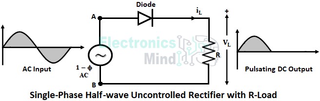
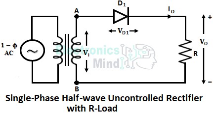
An uncontrolled rectifier is a type of ac to dc converter whose output voltage is fixed i.e., the output voltage is constant and cannot be varied.
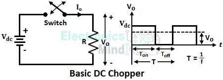
A dc chopper is simply a semiconductor switch (ON-OFF switch) that connects and disconnects the dc supply to the load at a rapid rate