In order to vary the magnitude of the ac voltage, the well-known and most commonly used device is a transformer. By using a step-up or step-down transformer we can increase or decrease the magnitude of the ac voltage at the output side. The transformers archives this change in magnitude by changing the value of its transformation ratio.
Other than using step-up and step-down transformers, we can vary the magnitude of the ac voltage by using AC Chopper. An ac chopper is a static switch that uses semiconductor devices for the variation of the ac voltage. It is also known as ac to ac chopper. This type of chopper is widely used in induction motor drive systems. It is also used in the design of ac synchronous mono-phase motors. Let us see the circuit and working of the single-phase ac chopper.
Single Phase AC Chopper :
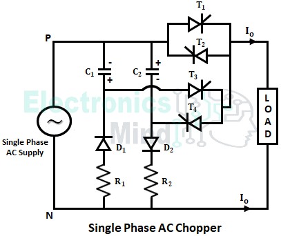
The circuit diagram of a single-phase ac chopper is shown below. It consists of four thyristors T1, T2, T3, and T4 out of which T1 and T2 are main thyristors, and T3 and T4 are auxiliary thyristors. The two capacitors C1 and C2 are the commutating capacitors for which the charging path is provided by the diodes D1 and D2 respectively.
Working of Single Phase AC Chopper :
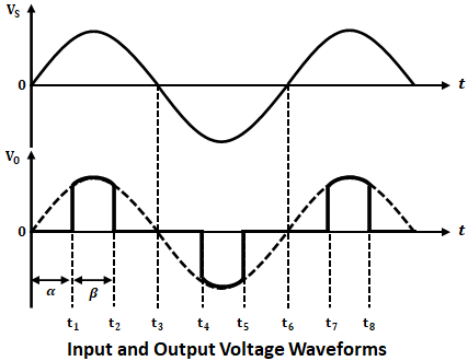
The chopping phenomenon in the above chopper circuit is provided by the thyristors T1 and T3 in the positive half cycle of the supply, and by the thyristor T3 and T4 in the negative half cycle of the supply. The below shows the input and output voltage waveforms. Let us understand the working in various operating modes.
Initially, for the positive half cycle, capacitor C2 charges through the path P → C2 → D2 → R2 → N with the polarity shown above. Similarly, for the negative half cycle, capacitor C1 charges through the path N → R1 → D1 → C1 → P with the polarity shown above.
Mode-I :
During the positive half cycle of the supply voltage, thyristor T1 is forward-biased. At instant t1, T1 is triggered with a firing angle (α), and thus the load current flows through the path P → T1 → Load → N.
Now at instant t2 (in the positive half cycle), auxiliary thyristor T3 will be triggered, due to which the capacitor C1 starts discharging through path C1+ → T3 → T1 → C1–.
When this discharging current exceeds the forward current of main thyristor T1, it will be commutated (i.e., it is turned OFF). Then after at instant t3, thyristor T3 will be also turned OFF automatically due to zero current and the negative half cycle starts.
Mode-II :
Now in the negative half cycle of the supply voltage, thyristor T2 is triggered at instant t4 due to its forward bais condition. Thus load current flows through path N → Load → T2 → P.
Similar to mode-I, auxiliary thyristor T4 is triggered at instant t5 to turn OFF main thyristor T2 using discharge current of capacitor C2. The path of the discharge current will be C2+ → T2 → T4 → C2– and thus T2 is turned OFF due to increase in its reverse current. At instant t6 thyristor, T4 will also be turned OFF due to zero current.
Further, in the next cycle, thyristor T1 will be again triggered to produce the next positive alternation, and once again the process repeats. Thus an ac voltage across the load will be generated. Therefore, it can be observed that the average output voltage of the chopper is different from the input voltage.
The frequency of the output voltage is determined by the thyristors switching rate. By varying the pulse width (β), the load power can be varied. The main advantage of ac chopper is that the fundamental input power factor is independent of pulse width (β) and is always remains unity.


