In order to get a controllable dc output voltage from the rectifier circuit, phase-controlled rectifiers are used. The phase-controlled rectifiers are also known as ac to dc converters. They employ thyristors whose triggering angle is varied to get a controllable dc output voltage.
In a semi or half-controlled converter, one quadrant operation is obtained i.e., only positive voltage and current will be obtained at the output. This type of converter circuit uses two thyristors and two diodes for the rectification process. Let us see the operation of a single-phase semi or half-controlled converter with bridge-type circuit configuration connected to an RL load.
The use of bridge-type configuration in converter circuits increases the average load voltage and improves the power factor and input current waveform. This type of circuit configuration is best suited to supply current to highly inductive loads and also there is no need for a center-tapped transformer which is needed in mid-point type circuit configuration.
Single-Phase Semi Converter With RL-Load :
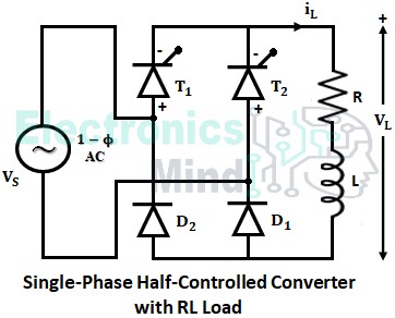
The below shows the circuit diagram of a single-phase semi or half-controlled converter supplying power to an RL load. When a converter delivers power to the RL load, the load current can be of two types. Either the load current can be continuous or it can be discontinuous depending upon the inductance of inductive load.
Discontinuous Current Mode of Operation :
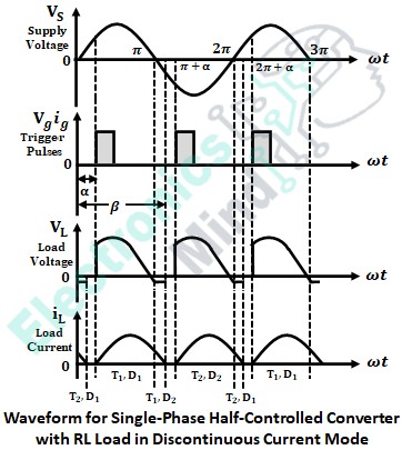
During the positive half cycle of the supply, thyristor T1 and diode D1 get forward biased, while thyristor T2 and diode D2 get reverse biased. Now, if T1 is triggered at a firing angle α it starts conducting. As a result, the load current iL starts flowing through the path VS → T1 → R → L → D1 → VS. As soon as VS reaches zero, VL also becomes zero.
Once VS enters into the negative cycle, T2 and D2 get forward biased and T1 and D1 get reverse biased. But, the load inductance L opposes a sudden change in current and hence releases the energy which is stored in the positive cycle. So, an EMF, e1 is induced in the inductor with opposite polarity. This EMF is responsible for maintaining the load current in the negative cycle before T2 is triggered.
Since T1 cannot be turned OFF until iL falls below its holding current value, iL continues to flow through the path L → D2 → T1 → R → L. Therefore, VL follows the negative cycle of supply voltage till β, where the load current becomes zero.
If the load inductance is not large enough to supply load current until T2 is triggered, then discontinuous conduction is obtained. So, iL falls to zero at an extinction angle, β where, π < β < (π + α). Therefore, from β to (π + α) both VL and iL remain at zero.
Once T2 is triggered i.e., at (π + α), the load current rushes through the path VS → T2 → R → L – D2 → VS. At the instant 2π, the load voltage falls to zero and once again the inductor releases the energy which has been stored in the negative cycle. This freewheel current flows through the path L → D1 → T2 → R → L.
Hence, VL will be again a small negative value which is equal to the sum of drops across T2 and D1. The entire operation repeats with a period of 2π as depicted by the waveforms shown above, which belongs to the steady-state operation.
Continuous Current Mode of Operation :
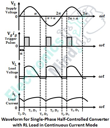
The continuous current mode of operation is obtained when the inductance of the load (shown in the above circuit) is large enough to supply the load current until the next thyristor is triggered.
So, in this mode of operation, extinction angle, β ≥ (π + α) and therefore the load current never remains at zero. Except for this, the entire operation is similar to the discontinuous current mode of operation. The waveform for this mode is shown below.
Need for Freewheeling Diode :
In the above two modes, we have seen that, due to inductive load, there will be a flow of load current even after phase reversal i.e., after completing each half cycle. This is because, due to the large inductive nature of the load, the load current has a tendency to flow continuously by finding an alternative path through the diode of the same arm of conducting SCR even after phase reversal. Thus there will be no control over the thyristor once it is triggered as seen in continuous and discontinuous modes.
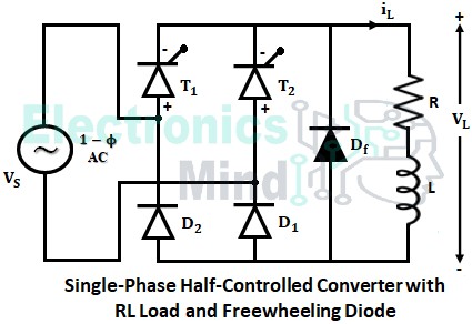
This problem can be overcome by connecting a diode in parallel with the load. This diode is known as a fly-back diode or freewheeling diode. When there is a phase reversal, this diode acts as the short-circuit path for inductive load current rather than passing it through the thyristors. Hence the thyristor regains its blocking state once there is a phase reversal in the supply.
The free-wheeling diode improves the load current waveform and increases the input power factor. It also eliminates the damage of the circuit components from the formation of voltage spikes during the turn-OFF period of thyristors and diodes.
Single-Phase Semi Converter With RL-Load and Freewheeling Diode :
The circuit diagram of a single-phase semi-converter with freewheeling diode connected to RL-load is shown in the below figure. The circuit is similar except for a freewheeling diode Df connected across the RL load.
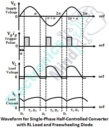
In this circuit, at ωt = π, T1 and D1 become reverse biased, whereas the freewheeling diode Df becomes forward biased. Hence, after ωt = π, the load current will be transferred from T1 D1 to Df. Now the current flows through the path Df → R → L → Df. During this period, the output gets short circulated through Df and the output voltage will be zero as shown in the below waveforms.
This process continues from π to π + α. When T2 is triggered at ωt = π + a, D2 and Df get forward biased. Now the load current shifts from Df to T2 D2, and again the load voltage follows the supply voltage till ωt = 2π. At ωt = 2π, T2 and D2 get reverse biased, and Df gets forward biased, and again the above process repeats.
We can see that the above load current and load voltage waveforms are similar to the waveforms of the converter without a freewheeling diode. But here load current due to inductive load is transferred back to it through the freewheeling diode Df rather than through the thyristor and diode combination T1 D2 and T2 D1.
Hence the freewheeling diode improves the circuit performance and also ensures commutation of thyristors at the end of each half-cycle providing a controlled load current under the triggering circuit.
Derivation for Single-Phase Bridge Semi Converter :
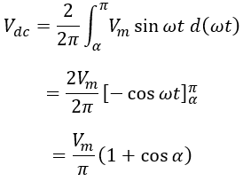
In both the single-phase semi converter circuits (with and without freewheeling diode) shown above. The source supplies the power to the load from α to π. From the above waveforms, upon neglecting the drops of diodes and thyristors. The average output voltage can be found from,
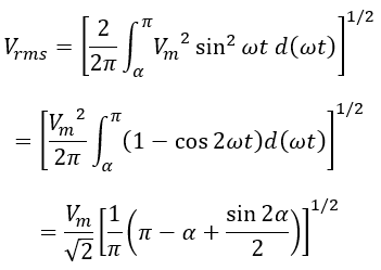
The RMS value of output voltage is given as,

