The ac voltage controller also called as AC Regulator is a static power electronic circuit that converts fixed ac to variable ac. It accomplishes this task without a change in frequency. It finds application in heating, lighting circuits, speed control of ac machines, fan regulators, etc, similar to the applications of an autotransformer.
The circuit of the ac voltage controller is based on either thyristors, TRIACs, SCRs, or IGBTs, which gives a variable ac at the output when their triggering angle is adjusted or varied. The output voltage is either increased, decreased, or kept constant by varying the RMS value of input fixed alternating voltage.
Classification of AC Voltage Controllers :
Depending upon the supply, ac voltage controllers are divided into two types. They are, - Single-phase ac voltage controller
- Half-wave voltage control or undirectional ac voltage controller
- Full-wave control or bidirectional ac voltage controller
- Three-phase ac voltage controller
- Half-wave voltage control or undirectional ac voltage controller
- Full-wave control or bidirectional ac voltage controller
- Half-wave voltage control or undirectional ac voltage controller
- Full-wave control or bidirectional ac voltage controller
- Half-wave voltage control or undirectional ac voltage controller
- Full-wave control or bidirectional ac voltage controller
In this article let us learn about single-phase ac voltage controllers.
Single Phase Half Wave AC Voltage Controller :
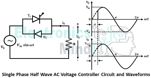
The below shows the single-phase half-wave or undirectional ac voltage controller circuit with output voltage and current waveforms.
Single-phase half-wave ac voltage controller consists of one thyristor in anti-parallel with one diode. The power delivered to the load will depend upon the firing angle of the thyristor. During the positive half cycle of supply voltage, only the thyristor is forward-biased. The thyristor will conduct from α to π.
At ωt = π, the thyristor will get turn-off for R-load. Now, when the negative half cycle starts diode will get forward biased (i.e., from π to 2π) and it conducts. Only the positive half cycle is controlled in a single-phase half-wave ac voltage controller due to this reason it is also known as a unidirectional ac voltage controller. The average value of the output voltage is given by,
Unidirectional ac voltage controllers are only suitable for low-power resistive loads like heating and lighting.
Single Phase Full Wave AC Voltage Controller :
The full-wave or bidirectional ac voltage controller uses two thyristors instead of one thyristor and diode. The two thyristors are connected in anti-parallel. Let see the working of full-wave ac voltage controller with resistive (R) load and resistive-inductive (RL) load.
Single Phase Full Wave AC Voltage Controller with Resistive Load :
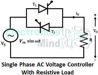
The power circuit diagram for a single-phase ac voltage controller with a resistive load is shown in the below figure. The power delivered to the load flows through thyristor T1 during the positive half-cycle and through thyristor T2 during the negative half-cycle.
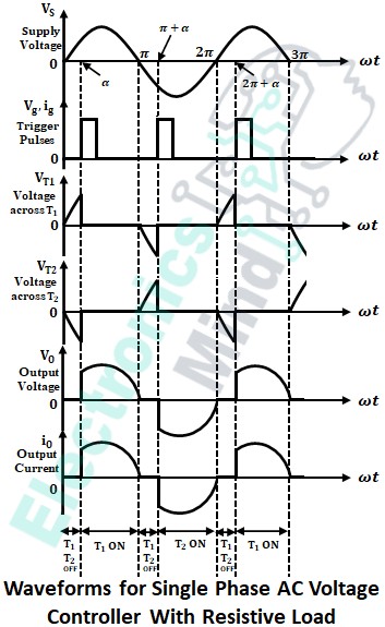
During the positive half cycle of the source voltage VS, SCR T1 is forward biased and SCR T2 is reverse biased. No conduction of load current takes place until thyristor T1 is triggered at some firing angle α. So, the entire supply voltage VS appears across thyristor T1 with the same polarity and across T2 with the reversed polarity. As soon as the thyristor T1 is triggered at the instant ωt = α, T1 starts conducting and the entire supply voltage VS, except the drop across T1, appears across the load resistance.
The above shows the waveforms for source voltage, gating signals, output voltage, output current, and the voltage across the SCRs. At ωt = π, the load voltage, the load current falls to zero and therefore T1 stops conducting. Thereafter thyristor T2 will be forward biased and T1 will be reverse biased and of course, there will be no conduction until T2 is triggered i.e., until (π + α).
As long as thyristor T1 in ON state, i.e., from α < ωt < π, voltage across T2 will be VT2 = – VT1 = -(ON-state voltage drop of T1). At ωt = (π + α), thyristor T2 is triggered and it starts conducting. Except for the small voltage drop across T2, the entire supply voltage appears across the load resistance and the load current flows. As long as T2 is in ON state, i.e., from (π + α) < ωt < 2π, voltage across T1 will be VT1 = -VT2 = -(ON-state voltage drop of T2).
This process goes on and continues for every cycle as shown in the waveform. For resistance load, the source current waveform will follow the source voltage waveform i.e., both the voltage and current of the source will be in phase with each other.
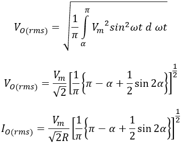
If the firing angles at which the thyristors T1 and T2 are same. The RMS value of output voltage and current with resistive load is given by,
Single Phase Full Wave AC Voltage Controller with RL Load :
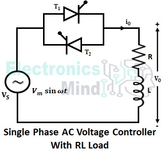
The below shows the single-phase ac voltage controller circuit with resistive and inductive load.
Operation When α ≤ Φ :
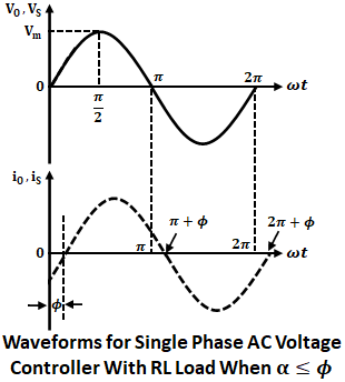
Consider α = Φ (load phase angle) i.e., the ac voltage regulator is operating under steady-state conditions. The conduction period of SCR T2 is from zero to Φ and from Φ to (π + Φ) SCR T1 will conduct and again from (π + Φ) to (2π + Φ) SCR T2 will conduct as shown in the waveform below.
When the firing angle α is reduced such that α < Φ, then if SCR T1 is triggered, it will remain OFF. Since SCR T2 is conducting a current, iT2 and the voltage drop across T2 will make SCR T1 reverse bias. The conduction of SCR T1 starts at Φ i.e. when voltage drop and the conduction current in T2 completely vanishes.
Thus, from Φ to (π + Φ), T1 will conduct. If T2 is triggered at a firing angle (π + α) < (π + Φ), then T2 will remain OFF because T1 is conducting a current iT1 and the voltage drop across T1 will make SCR T2 reverse bias. At ωt = (π + Φ), T2 will get turned ON since the voltage drop and conduction current in T1 at this instant becomes zero. Thus, SCR T2 will conduct from (π + Φ) to (2π + Φ). The voltage and current waveforms are shown in the figure below.
From the above waveforms, it is clear that there is no change in waveform from what they are at α = Φ. Therefore, when α is less than Φ, the output voltage of the ac regulator cannot be controlled. The ac output power can be controlled only for α > Φ. Thus, in order to get the desired output, the delay angle should be Φ < α < π. The below shows the operation when α > Φ.
Operation When α > Φ :
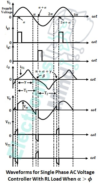
The waveform for input voltage and currents along with their outputs when α > Φ is shown below. The current Ig1 and Ig2 are the gating signals applied. During the positive half-cycles i.e., from 0 to π, thyristor T1 is forward biased and at angle ωt = α, thyristor T1 is triggered, and output current will be the current through the T1 i.e., iT1.
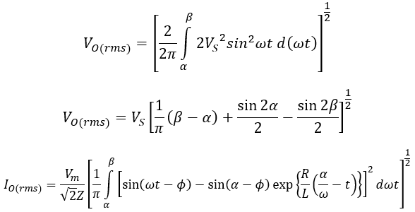
At the instant ωt = π, the load and source voltages become zero but, the current possesses some value due to the presence of inductance at the load side. So, thyristor T1 continues to conduct until the current flowing through it becomes zero. The angle at which thyristor current becomes zero is known as extinction angle β. So, output voltage and current are equal to source voltage and current from α to β respectively.
From angle β to (π + α), the value of load voltage and load current will be zero. At the instant ωt = (π + α), thyristor T2 is triggered and it starts conducting. So, the load current which is the same as current iT2 through T2 will flow in the reverse direction.
At the end of the first cycle i.e., at the instant ωt = 2π source voltage VS and load voltage VO becomes zero but the current doesn’t become zero. At the instant ωt = (π + α + γ) where, ωt = γ is known as conduction angle, the thyristor current iT2 becomes zero. This turns OFF thyristor T2 and it get reverse biased as shown in the waveform.

