Cycloconverter is an electronic device that converts input power signal of unregulated frequency to output power signal of desired frequency using power semiconductor devices. The single-phase to single-phase cycloconverters are of two types, step-up and step-down. In this article, we are going to learn about single-phase to single-phase step-down cycloconverter since most of the cycloconverters are of step-down type.
Generally, the circuit configuration of cycloconverters is either in mid-point type or in bridge-type. In this article, we will understand the cycloconverter operation with bridge-type circuit configuration while delivering power to resistive (R) and resistive-inductive (RL) load.
Single Phase to Single Phase Cycloconverter with R-Load :
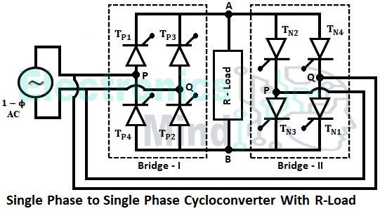
The single-phase to single-phase bridge-type cycloconverter is made using two single-phase fully-controlled converter circuits, bridge-I, and bridge-II as shown below. The two bridges are connected to the load in such a way that, they are in an anti-parallel connection. Also, the two bridges should not conduct at the same time, otherwise, a shortcircuit is produced at the input.
Whenever the load current is positive, bridge-I will be gated and gating pulses are not given to bridge-II. Similarly, when the load current is negative, bridge-II will be gated and gating pulses are not given to bridge-1. Firing pulses are applied in such a manner that only one bridge will be in conduction at a time, and shifting of the pulses from one bridge to another bridge is done based on the output frequency.
During the positive half cycle of the supply voltage, thyristors TP1, and TP2 are forward biased. At instant ωt = α, TP1 and TP2 are triggered and they start conducting current. Now, the load voltage is positive, with point A as positive and point B as negative, and the load current flows through the path,
At ωt = π, the negative half cycle of the supply voltage appears due to which thyristors TP1 and TP2 are turned OFF, and both the load voltage and load current become zero as shown in the waveform below.
Thyristors TP3 and TP4 are triggered at ωt = π + α and the load current and load voltage are zero till ωt = π + α. With the triggering of thyristors, TP3 and TP4 load current and load voltage increases and the current flows through the path,
Even in this period also the load current and load voltage are positive similar to when the thyristors TP1 and TP2 are in conduction as shown in the below figure.
At ωt = 2π, thyristors TP3 and TP4 are turned OFF and both the load voltage and load current become zero. Thus both positive and negative half cycles of the input supply are converted into two positive half cycles at the output. Now in order to obtain the negative half cycles at the output, bridge-II is operated.
During the next positive half cycle of the supply voltage, thyristors TN1 and TN2 are forward biased. Thus at instant ωt = 2π + α, thyristors TN1 and TN2 are triggered. Now the load voltage is negative and also the load current builds up in a negative direction. Till now the load current is flowing from A to B, but from time period 2π load current flows from B to A. The path of the load current in this half-cycle is,
From ωt = 3π, thyristors TN3 and TN4 will conduct. Hence, the load current and load voltage become negative for alternate cycles of input supply and it indicates that the input frequency is reduced to (1/2) at the output terminals.
Single Phase to Single Phase Cycloconverter with RL Load :
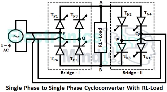
Suppose, if the load is inductive, the current through the SCR will not be reversed at the instant of line-voltage reversal and continues to flow even after it. This is due to the effect of load inductance since an inductor doesn’t allow the sudden change in current. Let us see the operation of a single-phase to single-phase converter with RL load.
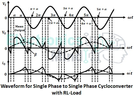
The below shows the waveforms when the cycloconverter supplies power to an inductive load. We have seen that with resistive load, at ωt = π, the load voltage and current become zero and the negative half cycle of the supply voltage appears which makes thyristors TP1 and TP2 turn OFF.
But in the above waveforms, due to inductive load, the load current doesn’t drop to zero immediately and it allows the conduction of thyristors TP1 and TP2 till ωt = β, where the value of β lies between π and (π + α) i.e., (π < β < π + α). At ωt = β, thyristors TP1 and TP2 are commutated and the load current becomes zero. At ωt = β thyristors TP3 and TP4 are triggered and they start conducting.
Thus when a cycloconverter supplies power to an inductive load, though the load voltage becomes zero at every phase reversal time, the load current still flows for some duration of time. The load voltage becomes negative for a part of the cycle till another SCR of the same group is fired and then the load voltage becomes positive again and vice-versa in case of a negative cycle. As a result, the load voltage remains zero for a period of time. In the above cycloconverter operation with RL load, we can see that load current is discontinuous. However, the load current can be continuous depending upon the load power factor and delay angle.
Hence, it can be concluded that two positive and two negative half cycles of the input are combined to produce one positive and one negative half cycle at the output i.e., stepping down the frequency to (1/2)nd of the input frequency. Similarly, there are other step-down cycloconverters that convert the input frequency to (1/3)rd, (1/4)th, etc, at the output terminals depending upon the requirement by the load.


