A class-B chopper is a type of chopper circuit whose operation is confined in the second quadrant of the Vo-Io plane. The term second quadrant means the output voltage and current of the chopper will occur only in the second quadrant of the output voltage and current (Vo-Io) plane. Thus a class-B chopper is also called second quadrant chopper.
In other words, the output voltage is always positive and the output current is always negative in a class-B chopper. The power flow in this type of chopper is always from load to source.
Circuit Diagram of Class-B Chopper :
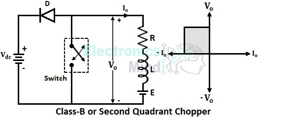
The circuit configuration of a class-B or second-quadrant chopper is shown in the below figure. The circuit consists of a diode (D) connected in series with the source and a switch connected across the load. The switch used in the chopper will be either a thyristor or transistor depending upon the power ratings.
Working of Class-B Chopper :
To operate a second quadrant chopper, the load must contain a dc source like a battery. Here in the above circuit, a motor load is assumed where R and L are the resistance and inductance of the motor, and E is the back EMF of the motor. The whole circuit is operated by turning ON and OFF the switch at regular intervals.
When Switch is ON :
When the switch is made to turn ON, the energy supplied by the load EMF drives current through L, R, switch, and back to load EMF as shown below. During this period, the inductor stores energy in it. Also when the switch is ON, the diode is reverse-biased due to which it acts as the open switch and hence the load is disconnected from the source.
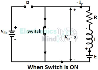
Since the load is isolated from the source, the load voltage or output voltage Vo becomes zero. Whereas the load current or output current Io supplied by the load EMF is in the opposite direction, thus the output current Io will be negative.
When Switch is OFF :
When the switch is turned OFF, the output voltage becomes Vo = (E + Ldi/dt) due to stored energy in the inductor. This voltage is greater than the source voltage due to which the diode gets forward biased and hence the current flows out of load to the supply through the diode as shown below.
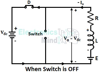
During the turn-OFF period of the switch, the output voltage Vo = Vdc and the output current Io remain in the same direction similar to when the switch is ON.
Thus the average load current or output current Io will be always negative irrespective of whether the switch is ON or OFF and the average output voltage will be positive. Hence the chopper operates only in the second quadrant of the Vo-Io plane.
Since output voltage can be either zero or positive and output current can never be positive, the output power can never be positive. It means that power flow takes place from load to source in the class-B chopper. This type of energy supply is possible only when the load is capable of providing continuous energy.
As the output voltage Vo = (E + Ldi/dt) is more than the source voltage Vdc, a class-B chopper is also called step-up chopper. The below shows the related waveforms of a class-B chopper.
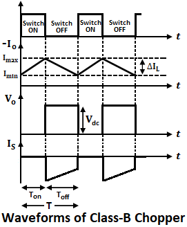
In the above waveforms, TON represents the turn-ON period of the switch. During this period, the voltage Vo will be zero and the current Io rises in the negative direction to the maximum value storing energy in the inductor. During the turn-OFF period of switch TOFF, Vo(avg) = Vdc, and the negative current Io flows through the source. Thus source consumes power which is supplied by load inductance and EMF.
Application of Class-B Chopper :
As we have seen that in a class-B chopper power flows from load to source. This type of energy transfer can be used in the regenerative braking of dc motors.
When breaks are applied to a dc motor, it acts as the generator for a short duration and the kinetic energy stored in the rotating parts of the motor will generate electric power. This electric power is returned back to the dc supply source.