A class-c chopper is a two-quadrant chopper that can operate in the first and second quadrants of the output voltage and current plane. It is a combination of class-A and class-B choppers. In this type of chopper, power can either flow from source to load or load to source and it can be used as a step-down or step-up chopper. A class-c chopper is also called as Two-Quadrant Class-A Chopper.
Circuit Diagram of Class-C Chopper :
The circuit topology of a class-c chopper is shown in the below figure. We know that a class-A chopper is a first-quadrant chopper and a class-B chopper is a second-quadrant chopper. A class-c chopper circuit is formed by the parallel combination of class-A and class-B choppers thus operating either in the first or in the second quadrant.
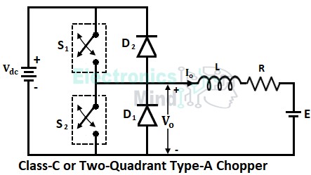
The circuit consists of two diodes (D1 and D2) and two transistors or thyristors (S1 and S2). These transistors or thyristors will act as switches whose switching is controlled by PWM signals.
Working of Class-C Chopper :
In order to operate a class-c chopper in the first quadrant, the output voltage and current should be positive. Whereas to get a second quadrant operation of a class-c chopper, the output voltage should be positive and the output current should be negative. Let us see the working of a class-c chopper separately for each quadrant.
First Quadrant Operation :
To obtain a first quadrant operation of a class-c chopper, switch S1 is turned ON due to which load gets connected across the dc supply source. Once the S1 is turned ON, the output voltage will become equal to the source voltage (i.e., Vo = Vdc) and the load current Io starts flowing in the forward direction storing energy in the inductor as shown below in figure-1.
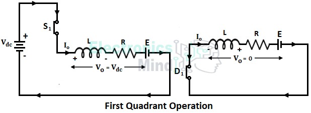
Now when switch S1 is turned OFF, the load current stops flowing in the circuit. Simultaneously, the inductor doesn’t allow a sudden drop in load current and therefore it induces a voltage with the reverse polarity to make the load current continue. The diode D1 free wheel the realized energy from the inductor as shown above in figure-2.
It can be seen that during the discharge period of the inductor also the load current remains in the same direction i.e., forward direction. Thus the output voltage Vo and output current Io will be positive and hence the chopper operates in the first quadrant.
Second Quadrant Operation :
For the second quadrant operation of a class-c chopper, the load must contain a dc source (for example back emf of a motor). Now the switch S2 is turned ON and the EMF (E) in the load forces a current in the reverse direction through the inductor and S2 as shown below in figure-1.
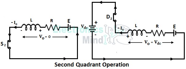
When switch S2 is turned OFF, the stored energy in the inductor starts realizing by forcing a current in the reverse direction through diode D2 to the supply. When D2 conducts, the output voltage will become equal to the source voltage (i.e., Vo will be positive).
It can be seen that the direction of the output current is in the reverse direction i.e., the output current Io will be negative. But the output voltage remains positive as same as the first quadrant operation. Hence the chopper operates in the second quadrant.
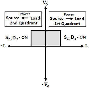
Therefore, the output voltage Vo = +Vdc i.e., Vo is positive, when S1 or D2 conducts and Vo is zero when D1 or S2 conducts. The output current Io is positive when S1 or D1 conducts, and Io is negative when S2 or D2 conducts. Below shows the waveforms of the class-c chopper.
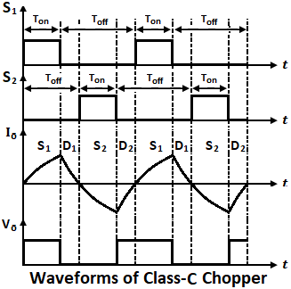
In the above waveforms, when S1 is ON, Io increases gradually to maximum value and Vo will be positive. When S1 is OFF, Vo is zero and Io decreases gradually through D1 which represents the discharge current of the inductor in the forward direction.
When S2 is ON, V2 is zero and Io increases negatively due to flow in a reverse direction. When S2 is OFF, Vo will be positive and Io decreases gradually from negative maximum through D2 which represents the discharge current of the inductor in the reverse direction.
Since the output voltage is always positive and the output current is either positive or negative, represents a reversible power flow. The power flows from source to load when the chopper operates in the first quadrant, whereas power flows from load to source when the chopper operates in the second quadrant. Also, it should be taken care that both the switches should not be turned ON at the same time because it results in short-circuiting of the dc supply source.
Application of Class-C Chopper :
A class-c type chopper is used for motoring and regenerative braking of dc motor. In the first quadrant operation, the dc motor operates in motoring mode where it receives power from the source. When breaking is applied to the motor, it behaves as the generator where it supplies power to the source.