What is Class-D Chopper?
A class-D chopper is a two-quadrant chopper that can operate in first and fourth quadrants of output voltage and current plane. In this chopper power can either flow from source to load or load to source depending upon the quadrant operation. A class-D chopper is also called as Two Quadrant Type-B Chopper. In this article let us see the circuit diagram and working of a class-D chopper.
Circuit Diagram of Class-D Chopper :
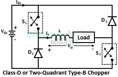
The circuit configuration of a class-D chopper is shown in the below figure. It consists of two switches S1 and S2 and two diodes D1 and D2. The switches are generally power semiconductor devices which can be a transistor or a thyristor whose switching is controlled by controlling their gate signal.
Working of Class-D Chopper :
In order to operate a class-D chopper in the first quadrant, the output voltage and current of the chopper must be positive. Whereas in order to operate a class-D chopper in the fourth quadrant, the output voltage should be negative, and the output current should be positive. Let us see the working of a class-D chopper in the first and fourth quadrants separately in detail.
First Quadrant Operation :
In the first quadrant operation of a class-D chopper, switches S1 and S2 are turned ON. Once the two switches are turned ON, the load starts receiving power from the source, and thus load current will flows in the circuit through the path Vdc, S1, load, S2, and back to the Vdc as shown below.
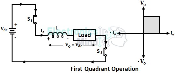
During the interval when S1 and S2 are ON, the output voltage Vo will be equal to the source voltage Vdc and the output current Io increases exponentially. The inductance in the load stores energy during this period. The diodes D1 and D2 will remain in OFF-state since they are reverse-biased.
Hence, we can see that the output current Io and output voltage Vo remain positive during the whole period, and hence a first quadrant operation of a class-D chopper is obtained.
Fourth Quadrant Operation :
Now when the switches S1 and S2 are turned OFF. The load gets disconnected from the source and the load current stops flowing in the circuit. But at the same time, the inductive nature of the load doesn’t allow a sudden drop in load current, and hence a huge amount of voltage is induced in the inductor in the reverse direction.
Thus the polarity of the inductor gets reversed and the inductor starts discharging in the reverse direction. This causes the diodes D1 and D2 to forward bias and they start conducting. The energy stored in the inductor is realized gradually through the load, D2, Vdc, D1, and back the load as shown below.
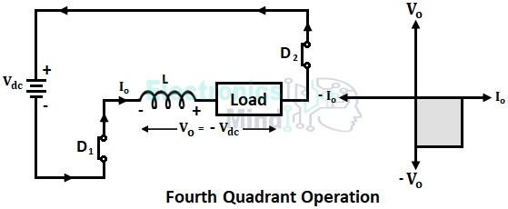
We can see that the direction of the output current Io has not changed but the polarity of output voltage Vo is reversed. Thus output current Io remains positive whereas output voltage Vo will be negative and hence a fourth quadrant operation of the chopper is obtained.
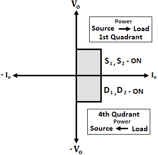
Therefore, when the switches are made to conduct the chopper operates in the first quadrant, and current flows from source to load. When the switches are OFF the chopper operates in the fourth quadrant, and current flows from load to source as illustrated below.
The below shows the waveforms for class-D chopper when the turn-OFF period of switches is more than the turn-ON period (i.e., TOFF > TON).
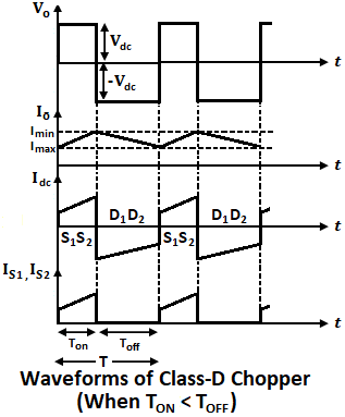
We can see that during the turn-ON period TON of switches, the output voltage Vo will be positive, and output current Io will gradually increase to maximum value due to the presence of inductance. Whereas during the turn-OFF period TOFF of switches, the output voltage Vo will become negative, and output current Io will gradually decrease due to the discharge of the inductor current.
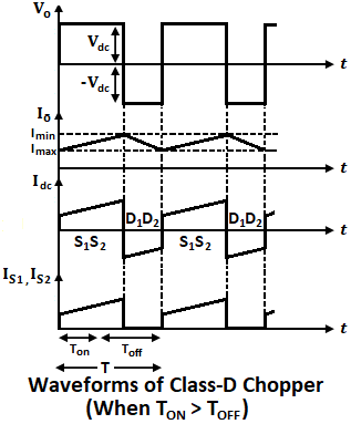
During the turn-OFF period of switches, the source current Idc will become negative which represents the current flowing from load to source. Similarly, the waveforms when the turn-ON period of switches is more than the turn-OFF period (i.e., TON > TOFF) are shown below.
The average value of output voltage is given by,
From the above equation, we can conclude that the average output voltage will depend upon turn-ON and turn-OFF periods.
- When TOFF > TON (if duty cycle < 0.5), the average output voltage Vo will be negative.
- When TON > TOFF (if duty cycle > 0.5), the average output voltage Vo will be positive.
- When TOFF = TON (if duty cycle = 0), the average output voltage Vo will be zero.
Therefore, the average output voltage of a class-D chopper can be either positive or negative depending upon the duty cycle. But the average output current of a class-D chopper will always remain positive irrespective of the duty cycle.