A class-E chopper is a type of dc chopper that has the capability to operate in all four quadrants of output voltage and current plane i.e., the output voltage and current can be positive or negative. In a class-E chopper power can either flow from source to load or load to source by operating it in different quadrants. A class-E chopper circuit is also called as a four-quadrant chopper.
Circuit Diagram Of Class-E or Four-Quadrant Chopper :
The below figure shows the circuit configuration of a Class-E or Four-Quadrant Chopper. A class-E chopper circuit is formed by the parallel combination of two class-C chopper circuits. The circuit consists of four switches (S1, S2, S3, and S4) and four diodes (D1, D2, D3, and D4).
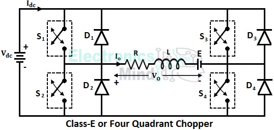
The switches used are power semiconductor devices mostly transistors (IGBT, MOSFET, or BJT). The transistors are turned ON and OFF by using pulse width modulation signals. Let us see the working of a class-E chopper with RL (resistance and inductance) load.
Working of Class-E Chopper :
The operation of a class-E chopper in four quadrants is obtained by turning ON different switches and diodes in pairs of various combinations. Let us see the working of a class-E chopper or four-quadrant chopper separately for each quadrant in detail. Before discussing the operation of a class-E chopper, it should be noted that,
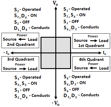
- To obtain first quadrant operation, the output voltage Vo and current Io should be positive.
- To obtain second quadrant operation, output voltage Vo should be positive, and output current Io should be negative.
- To obtain third quadrant operation, output voltage Vo and current Io should be negative.
- To obtain fourth quadrant operation, output voltage Vo should be negative, and output current Io should be positive.
First Quadrant Operation :
In order to operate a class-E chopper in the first quadrant, the switches S1 and S4 are made to function. When both switches S1 and S4 are turned ON, the load gets connected across the source. Thus load voltage becomes equal to the source voltage, and the load current starts flowing in the circuit from source, S1, load, S4, and back to the source as shown below in figure-1.
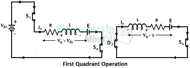
When S1 and S4 are ON, the load inductor stores energy. Then after switch S1 is turned OFF and now the load current due to inductance starts free wheeling through S4 and diode D2 as shown in figure-2.
Hence we can see that initially when switches S1 and S4 are ON, the output current Io and voltage Vo will be positive. Also during the discharge period of the load inductor, the load current and voltage remain positive. Thus a first quadrant operation of a class-E chopper is obtained. In the first quadrant operation power always flows from source to load and the circuit operates as a step-down chopper.
Second Quadrant Operation :
In the second quadrant operation of a class-E chopper, the load will act as the dc source (generator). Here switch S2 is operated while keeping other switches OFF. When switch S2 is turned ON load EMF E, drives current through the load, S2, D4, and back to E as shown in figure-1 below.
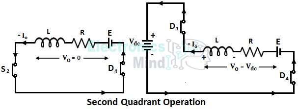
During the conduction of current through S2 and D4, the load EMF stores energy in the inductor L. Now when the switch S2 is turned OFF, the charged inductor starts discharging along with the load EMF (i.e., E + Ldi/dt) through D1, source, and D4 as shown in figure-2 above.
Thus we can see that, the average output current Io is negative due to flow in the reverse direction, and since (E + Ldi/dt) is more than the source voltage, the average output voltage Vo remains positive. Hence a second quadrant operation of a class-E chopper is obtained. Since the load supplies current, power flows from load to source in the second quadrant operation.
Third Quadrant Operation :
For the third quadrant operation of a class-E chopper, load voltage and current should be negative. In order to operate a class-E chopper in the third quadrant, the polarity of load emf E must be reversed. Now the switches S2 and S3 are turned ON connecting the load across the source. When S2 and S3 are ON, load current flows from source to S2, load, S3, and back to source as shown below in figure-1.
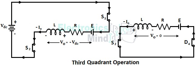
During the interval when S2 and S3 are ON, the inductor stores energy and output voltage Vo = -Vs. After a certain time, switch S3 is turned OFF, and thus load gets disconnected from the source. Now inductor starts releasing its stored energy through S2 and D4 as shown above in figure-2.
Hence we can notice that the polarity of the output voltage Vo is opposite and the flow of output current Io is in the reverse direction. Therefore both the average output voltage and output current are negative. Similar to the first quadrant power flows from load to source in the third quadrant operation.
Fourth Quadrant Operation :
To get the fourth quadrant operation, the polarity of load EMF is kept reversed and the load must contain a dc source. To obtain the fourth quadrant operation switch S4 is operated, thus load EMF drives current through S4, D2, and load which is shown below in figure-1.
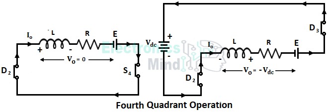
During the conduction of S4 and D2 load inductor is charged. Once the switch S4 is turned OFF, the inductor starts discharging and current is fed back to the source through D4, source, and D2.
Hence, when S4 is ON output current Io is positive and output voltage Vo will be zero. Whereas when S4 is OFF output current Io will be still positive but output voltage Vo = -Vs (i.e., Vo is negative). Therefore, Io will be positive and Vo will be negative which leads to a fourth quadrant operation of the chopper. Similar to the second quadrant, power flows from load to source in the fourth quadrant operation.
The below figure illustrates the characteristics of the class-E chopper in four quadrants.
Application of Class-E Chopper :
A class-E chopper is used for a reversible regenerative dc motor drive where it can reverse the direction of rotation and breaking in either direction.
In the first quadrant operation, the motor operates in the forward motoring mode where it rotates in the forward direction due to positive output voltage and current. In the second quadrant operation, the motor operates in the forward braking mode where it acts as the generator. In this mode, braking is applied to the motor which opposes the motion due to which mechanical energy is converted into electrical energy which may be supplied back to the mains.
The third quadrant operation is called reverse motoring mode where the motor direction of rotation is reversed due to negative output voltage and current. In the fourth quadrant, the motor operates in a reverse braking mode where it acts as the generator supplying power back to the mains.
Conclusion :
From the above-discussed circuit diagram and operation of class-E, we can conclude that,
- When the chopper operates in the first and third quadrants, the average output voltage is less than the input voltage which means the circuit works as the step-down chopper.
- When the chopper operates in the second and fourth quadrants, the average output voltage is greater than the input voltage (i.e., E + Ldi/dt > Vs) which means the circuit works as the step-up chopper.
- It should be taken care that at any instant switches on the same side should not be turned ON otherwise it results in a dc short circuit.