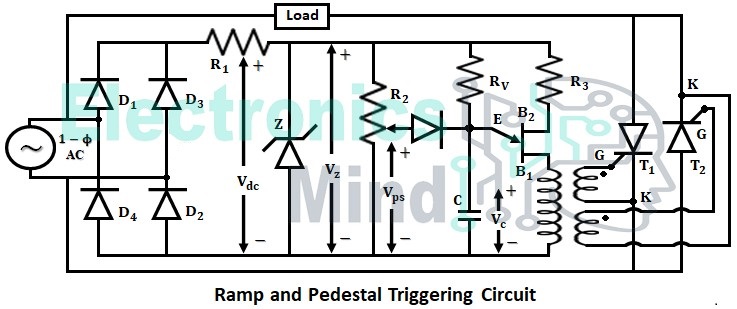
Ramp and pedestal triggering is a modified version of ramp triggering. In this firing circuit, two thyristors T1 and T2 are connected in an anti-parallel manner for controlling the firing angle and thereby controlling the output power. The below shows the circuit configuration for ramp and pedestal triggering.
In the circuit shown above,- D1, D2, D3 and D4 = Diodes form full-wave bridge
- Vps = Pedestal voltage
- Vs = Source voltage
- VC = Capacitor voltage
- Vz = Voltage across zener diode.
- T1, T1 = Thyristors.
In this firing circuit, variable resistor R2 is used to control the pedestal voltage Vps, R2 acts as the potential divider. By adjusting the potentiometer R2, such that Vps is less than the threshold value of UJT (i.e., ηVz), the capacitor then starts charging through RV. When the capacitor voltage VC equals threshold voltage UJT is turned ON and pulse voltage is given to thyristors T1 and T2.
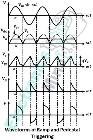
- SCR T1, which is in the forward-biased state is turned-ON in the interval 0 to π. After SCR T1 is turned-ON, VC reduces to Vps and then to zero at ωt = π.
- SCR T2 is forward biased and is turned-ON at ωt = π. So, T1 is turned-ON from ωt = 0 to ωt = π and SCR T2, is turned-ON from ωt = π to ωt = 2π. Hence, an alternating load voltage is produced as shown in the below waveforms.
Charging of capacitor is done through Rv and diode D. If the value of Vps is less, then capacitor takes more time to reach threshold voltage and hence the firing angle delay occurs which makes output voltage less. Hence, it can be concluded that output voltage is directly proportional to Vps.
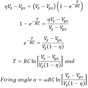
Time taken for the capacitor to charge from Vps to ηVz, can be derived as follows,
In the above equation RC is the time constant. From the above equation, we have,
Where ω is the input frequency and η is the intrinsic stand-off ratio of UJT.


