There are many ways to turn ON a thyristor, like forward-voltage firing, dv/dt triggering, temperature triggering, light triggering, and gate triggering. But other than these methods, the most commonly employed method to turn-ON a thyristor is by controlling the gate pulse.
The circuit used for turning ON the thyristor by giving gate pulses is called the Firing or Triggering Circuit of SCR. But in order to employ the firing circuit method for turning ON thyristor, the circuit must fulfill some conditions,
Conditions for Triggering or Firing Circuits of Thyristors :
Certain conditions are to be met for firing the thyristors are, - Gate current should be of sufficient amplitude and should flow in the circuit for the required duration.
- Voltage pulses should be fed to the driver circuit first and then to the gate-cathode circuit.
- For a circuit with more than one thyristor, the gate current for each thyristor must be provided at the desired instant of time.
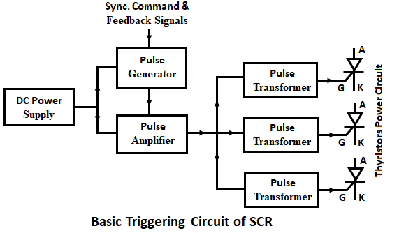
The general layout for firing the thyristor is shown below.
The firing circuit consists of a control circuit, a driver circuit, and a power circuit. The output of the pulse generator is fed to the pulse amplifier for amplification. Amplified pulses are given to the pulse transformer through shielded cables. The pulse transformer separates the low-voltage gate-cathode circuit from the high-voltage anode-cathode circuit.
Triggering or Firing Circuits of Thyristor or SCR :
The most commonly used firing or firing circuits for thyristor or SCR are,- Resistance Firing Circuit (R-Firing),
- Resistance-Capacitance Firing(RC-Firing),
- UJT-Firing Circuit.
Resistance Firing Circuit (R-Firing) :
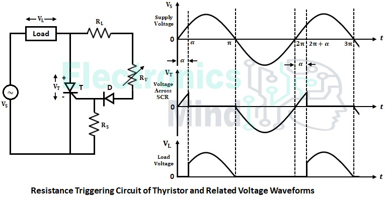
The below shows the circuit configuration and waveforms of the resistance firing circuit. This firing circuit is the simplest method of controlling the firing angle of SCR. In this firing circuit, the firing angle can vary over a limited range of 0° to 90°. Instead of giving gate pulses to the thyristor, an ac supply is given to the gate terminal for firing.
Working of Resistance Firing Circuit (R-Firing) :
The working of the resistance firing circuit is as follows,- During the positive half-cycle of the voltage source VS, thyristor, T is forward-biased, but it doesn’t conduct because of insufficient gate current. Hence, load voltage VL is zero.
- As voltage source VS increases, thyristor and diode both are forward-biased, and gate current IG flows in the circuit. When gate current IG reaches to value equal to IG(min), the thyristor is turned-ON and load voltage follows source voltage, and the voltage drop across the thyristor is equal to the on-state drop.
- During the negative half cycle of the supply voltage, the thyristor is reverse-biased, and hence it is turned OFF. Thus load voltage VL becomes zero and voltage across the thyristor VT will be equal to source voltage VS.
The diode in the gate circuit prevents the reverse voltage of the thyristor during the negative half-cycle from exceeding peak reverse voltage. The limiting resistance RL placed between anode and gate of thyristor limits the gate current not to exceed peak gate current IG(max).
From the waveforms above, the firing angle and the output voltage can be controlled by varying the variable resistance RV. If RV is large, then the current will be small, and hence firing angle (α) increases and vice versa.
Advantages of Resistance Firing Circuit :
- The firing circuit is very easy and simple to operate.
- The firing angle can be varied from 0° to 90°.
- By using a capacitor and a diode, the limited firing angle issue is resolved.
Disadvantages of Resistance Firing Circuit :
- Limited firing angle i.e., up to 90° only.
- The firing angle is totally dependent on the minimum gate current of thyristors.
- The value of minimum gate current changes between the thyristors.
- It is a temperature-dependent circuit.
Resistance-Capacitance Firing Circuit (RC-Firing) :
The limitations of the resistance firing circuit can be overcome by using a resistance-capacitance firing circuit. Using an RC-firing circuit the firing angle can be controlled from 0 to 180 electrical degrees. There are two types of RC-firing circuits,
- RC half-wave firing circuit, and
- RC full-wave firing circuit.
RC Half-Wave Firing Circuit :
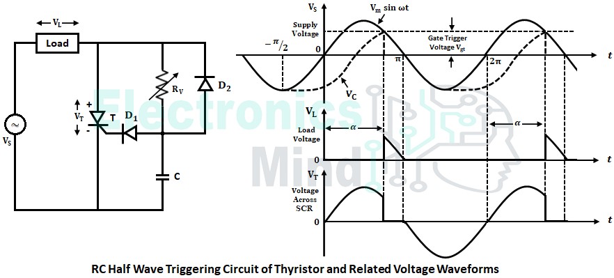
The above figure illustrates the RC half-wave firing circuit. The capacitor charges to the negative peak of the ac voltage in every negative half-cycle through the diode D2. During the positive half-cycle, it begins to charge through the resistance RV. When the voltage across the capacitor reaches the required positive value, the thyristor is fired and the capacitor voltage remains almost constant.
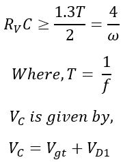
The diode D1 prevents the breakdown of the gate-cathode junction during the negative half-cycle. For power frequencies, the value of RV C for zero output voltage is empirically given by,
The maximum value of variable resistance RV is given by,
If the value of RV is high, then the capacitor takes more time to charge. Hence the firing angle is more but the average output is low and vice-versa. In order to have more output, the value of RV should be less.
RC Full-Wave Firing Circuit :
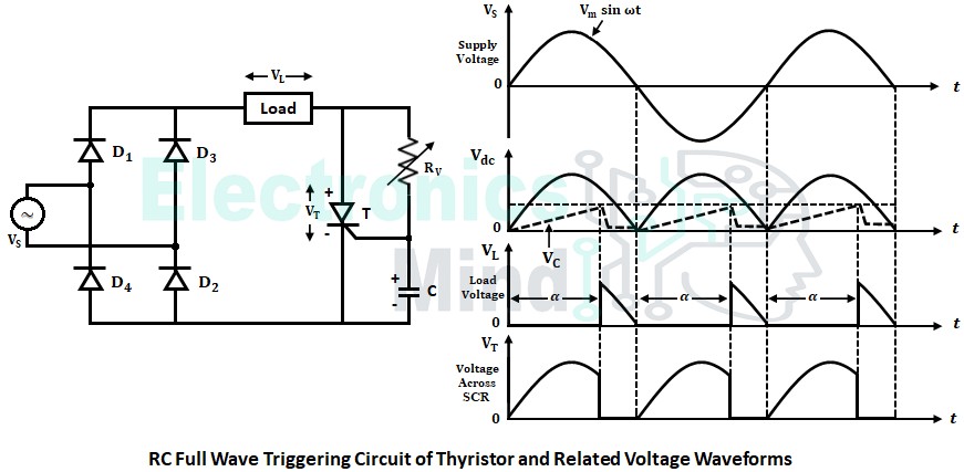
The advantages of a full-wave firing circuit over a half-wave firing circuit are, - Power can be delivered to load both during positive and negative half-cycles because of the full-wave bridge diode.
- The firing angle can be controlled from 0° to 180°.
- The power delivered to the load is doubled.
- The output voltage is present even in the negative half cycle.
The below figures illustrates the RC full-wave firing circuit.
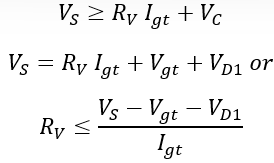
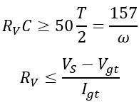
Initially, the capacitor starts charging from zero voltage, and this low voltage is achieved by the clamping action of the SCR gate. When VC reaches Vgt, SCR is turned-ON and ac line voltage which is rectified into dc by a full-wave diode bridge appears across the load. In this circuit, RVC and RV are given by,
Advantages of RC Firing Circuit :
- The firing angle limitation in the R-firing circuit is overcome by the RC-firing circuit.
- The firing angle range is between 0 and 180°.
- The circuit is cheap, simple, and also acts as a snubber circuit.
Disadvantages of RC Firing Circuit :
- The values of RV and C changes with respect to temperature.
- The firing angle depends upon the RC time constant.
- Supply fluctuations have effects on firing angle.
- It is only applicable in power circuits where only one thyristor is used.
- It can be used only in open-loop control systems.
UJT Firing Circuit :
The above discussed R-firing and RC-firing circuits produce continuous gate pulses due to which there will be quite high power dissipation at the gate circuit of the thyristor. This power dissipation in the gate circuit can be reduced by using a UJT in the firing circuit. The UJT will work as a relaxation oscillator that produces sharp repetitive pulses with good rise time, and it also has good frequency stability under voltage fluctuations and temperature variations.
In the above UJT firing circuit, the UJT starts conducting once the value of the voltage across the capacitor is equal to or more than the peak voltage VP value of the UJT. Now the capacitor starts discharging, and once its voltage decreases to the valley voltage VV of UJT, the UJT will be turned OFF. The capacitor again gets charged to supply voltage and the above process repeats.
Thus whenever UJT conducts it produces pulses at the gate terminal of the thyristor as shown in the waveform. The capacitor charging time depends upon the value of variable resistance RV. Therefore, by varying the value of RV the firing angle can be varied.

