A Step-down chopper is basically a high-speed semiconductor switch. The switch can either be a power BJT, power MOSFET, transistor, or SCR depending upon the voltage, current and switching rate required. With the help of the switch (i.e., chopper) the dc supply is connected and disconnected to the load very rapidly such that the average dc load voltage from the chopper will be less than the source voltage i.e., the output voltage of the chopper is stepped down.
Working of Step Down Chopper With R Load :
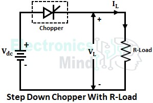
The below shows the circuit configuration of a step-down chopper connected to an R-load. A chopper is connected between the resistive load and the source. The chopper is fed from a fixed dc supply and stepped-down dc output from the chopper is given to the resistive load.
- When the chopper is switched ON, the load is connected in the circuit and the load voltage VL follows the source voltage Vdc i.e., VL = Vdc.
- When the chopper is turned OFF, the load is disconnected from the circuit, due to which the load voltage and load current become zero. Since the load is purely resistive, the load current will be same as that of load voltage but with a lesser magnitude.
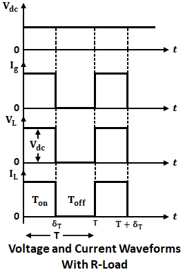
The voltage and current waveforms when the chopper is connected to a resistive load are shown below.
In the above waveform, from time period t = 0 to δT, the chopper is turned ON. Thus from t = 0 to δT load voltage VL will be equal to source voltage Vdc and load current IL will follow the load voltage VL. At t = δT chopper is turned OFF and hence load voltage and the current become zero. Again the chopper is turned ON at t = T and the same process repeats.
Working of Step Down Chopper With RL Load :
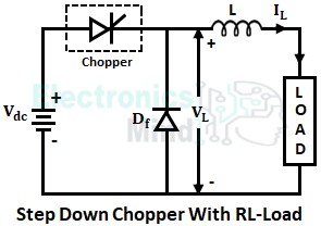
The circuit configuration for a step-down chopper with RL-load is shown in the below figure.
Generally, choppers are used to drive separately excited dc motors. The armature in the dc motor is represented by a combination of resistance and inductance. Hence, motors are considered as RL-load. For a step-down chopper, with RL-load, two modes are possible for the load current. They are,
- Continuous load current, and
- Discontinuous load current.
Continuous Load Current :
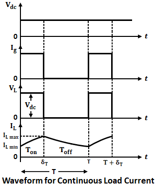
If the value of the load inductance is very high, then the continuous load current is obtained. When the chopper is turned on for a period of 0 to δT, the RL load is connected in the circuit, load voltage VL follows source voltage Vdc the load current rises from its lower limit and reaches the maximum value at t = δT.
When the chopper is turned OFF for a period of δT to T, the load voltage becomes zero but the load current does not become zero due to the presence of load inductance. This is because an inductor doesn’t allow a sudden change in the current.
Thus once the chopper is turned OFF, the stored current in the load inductance free-wheels through the free-wheeling diode Df as shown above. Then after the load current decreases gradually and reaches its lower limit as shown in the below waveforms.
Discontinuous Load Current :
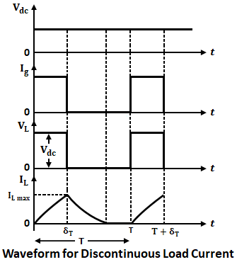
If the value of load inductance is small then a discontinuous load current is obtained. During the chopper OFF period, load voltage becomes zero, and load current decreases. Then after the load current becomes zero at a certain instant of time and it remains zero until the chopper is turned ON again i.e., until t = T. Hence, in this way discontinuous current appears in the load. Below shows the waveform for the discontinuous load current.
Derivation of Average Output Voltage :
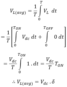
From the waveforms, we can see that the load voltage flows only during the turn ON period (TON) of the chopper. The average output voltage is given by,
Where δ = TON/(TON + TOFF) = TON/T is known as duty cycle. Thus by varying the duty cycle (δ) from 0 to 1, we can obtain load voltage from 0 to Vdc. Hence the load voltage will be always less than the input voltage, thereby calling it a Step-Down Chopper.

