In most of the industrial and domestic applications, there is a requirement for a variable dc supply which in turn leads to need for a device that can convert a fixed dc supply to a variable dc supply. A dc chopper is a dc to dc converter that converts fixed dc supply to variable dc supply. In simple dc chopper is similar to an autotransformer in ac circuits and can be used as a step-up or step-down of the dc input voltage.
Though there are different methods to obtain variable dc supply like converting fixed dc supply to ac by using an inverter which is then converted into variable dc supply by a controlled rectifier or by using a step-up or step-down transformer after inverter which is then converted into variable dc supply by an uncontrolled rectifier.
However, a dc chopper is a single-stage dc to dc converter unlike more than one stage i.e. converting dc to ac and then ac to dc. Thus a dc chopper is more efficient, smaller in size, and low in cost due to which it is mostly used in many applications.
Principle of DC Chopper :
DC choppers consist of semiconductor devices like thyristors, BJT, MOSFET, IGBT, etc, that act as the switch which connects and disconnects the supply to load at a rapid rate due to which the average dc voltage supplied to the load changes and thus a variable dc supply is obtained from a dc chopper.
On the basics of output voltage, dc choppers are mainly divided into two types step-up choppers and step-down choppers. In this article let us learn about the step-up chopper.
Step Up Chopper :
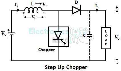
A step-up chopper is similar to a step-up transformer whose output voltage is greater than the input supply voltage. The below shows the circuit configuration of the step-up chopper.
When chopper CH is ON, the supply current flows the path,
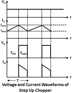
The inductor L stores energy in this state. The inductor chosen for this circuit is supposed to have a higher value of inductance L so as to reduce the ripples in the output voltage and also to obtain the continuous current.

Now when the chopper CH is turned OFF the inductor current is forced to flow through the series combination of diode and load. This is because of the property of the inductor, i.e., the inductor current cannot fall to zero instantaneously. Since stored energy in the inductor is negative it adds to the supply voltage and thus the voltage across the load is given by,
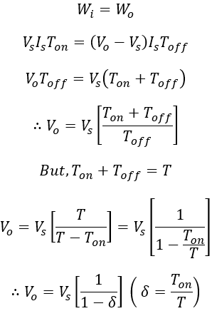
Therefore the output voltage exceeds the input source voltage. During the ON period of the chopper, the voltage across the inductor is equal to the supply voltage (neglecting the voltage drop in SCR). The energy stored in the inductor during the chopper ON period is given by,
Now when the chopper is in the OFF state the voltage across the inductor will be difference of the average output voltage and supply voltage. The energy stored by the inductor is delivered to the load is,
Considering the system to be lossless, under steady state condition, we have,
Hence, by varying the duty cycle (δ) the output voltage can be varied. If the duty cycle becomes zero, the output voltage Vo = Vs and if duty cycle (δ) = 1 then Vo = ∞. Here, we can observe that the output voltage Vo is greater than or equal to the input voltage Vs. Hence the circuit is called a step-up chopper.
A step-up chopper is used in regulated dc power supplies and regenerative braking of dc motors. A capacitor is used in parallel with the load to ensure constant and continuous output voltage.


