In ac voltage controllers, it is possible to control the output voltage, but not the frequency, and also the harmonic quantity at the output of ac voltage controllers is high. The variable-frequency at the output can be obtained from the stage conversion i.e., fixed ac to variable dc (e.g., controlled rectifiers) and variable dc to variable ac at a variable frequency (e.g. inverters).
So, for the output frequency to be controlled, we need to have the dual apparatus, but with the “cyclo converters”, we can wipe out the need for the dual apparatus. Moreover, with the use of the cycloconverters, all the lower-order harmonics are reduced to zero.
What is Cycloconverter?
A cycloconverter is a single-stage frequency changer that converts alternative voltage from one fixed frequency to another frequency without the help of an intermediate dc link. Due to the absence of intermediate dc link, the cycloconverters are more efficient. The output voltage and frequency of the cycloconverters can be easily varied continuously and independently by means of a control circuit.
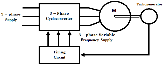
The figure below shows the block diagram of a 3-phase cycloconverter. When a 3-phase supply is fed to a 3-phase cycloconverter, it converts the 3-phase 50 Hz supply into a 3-phase variable frequency (may change from zero to 50 Hz or more). This variable frequency 3-phase supply is fed to a 3-phase motor whose speed control is required.
The tachogenerator attached to the 3-phase motor checks the speed of the motor with the preset value. If there is any difference in accordance with the preset value and actual value of the motor speed, then the proportionate signals will be sent to the firing circuit to change the firing angle. Accordingly, the output frequency and hence the motor speed also varies.
Salient Features of Cycloconveters :
- A cycloconverter is a one-stage conversion device that converts ac input power at supply frequency to ac output power at load frequency.
- The main feature of a cycloconverter is that it has the facility for continuous and independent control over the output frequency and the output voltage.
- It can also provide a fixed output frequency from a variable input frequency.
- The cycloconverters are capable of transferring power in any direction, i.e., either from the source to load or from the load to the source.
- For very low-speed applications, the cycloconverters are preferable as, for low output frequency the output voltage sinusoidal waveform is of high quality.
Types of Cycloconverters :
Cycloconverters are basically line-commutated dual converters that are operated in a particular manner to obtain the required output. Primarily cycloconverters are two types,- Step-up cycloconverters, and
- Step-down cycloconverters.
Step-up Cycloconveters :
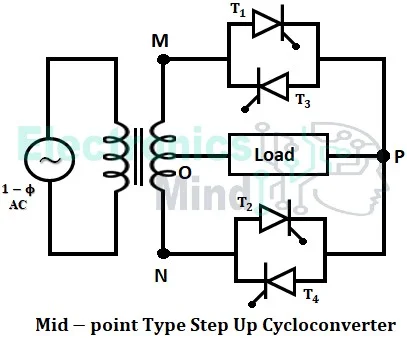
Step-up cycloconverters are the converters in which the output frequency obtained is greater than the input supply frequency. The circuit diagram of a single-phase midpoint type step up cycloconverter is shown in the below figure.
The circuit consists of four thyristors T1, T2, T3, and T4. Depending upon the generation of positive half-cycle and negative half-cycle these thyristors are divided into groups, thyristors T1 and T2 form the positive group, whereas thyristors T3 and T4 form the negative group.
A mid-point cycloconverter uses a single-phase transformer whose secondary winding is tapped at the center. The load is connected between points O and P. The thyristors are triggered depending upon the polarities of points M and N of the transformer.
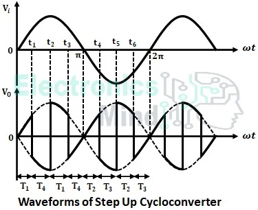
When the supply is given to the single-phase mid-point cycloconverter, point M is positive with respect to point O. For the positive half cycle, thyristor T1 is triggered from 0 to t1, thus the obtained output voltage is positive. At the instant t1, the thyristor T1 is forced commutated and thyristor T4 is turned ON so that the load voltage becomes negative as shown in the below waveforms.
At π, T4 is forced commutated and T2 is turned ON, thus the output voltage is positive. At the instant t4, the thyristor T2 is forced commutated and T3 is turned ON, and thus the output voltage is negative. In this manner the sequence continues, as a result, the output voltage frequency is higher than the supply frequency.
Step-down Cycloconveters :
Step-down cycloconverters are the converters in which the output frequency obtained is less than the input supply frequency. Most of the cycloconveters used are of stepped-down type. The step-down type cycloconverters are again classified as,- Single-phase to Single-phase Cycloconverters,
- Three-phase to Single-phase Cycloconverters, and
- Three-phase to Three-phase Cycloconverters.
Single Phase to Single Phase Cycloconverters :
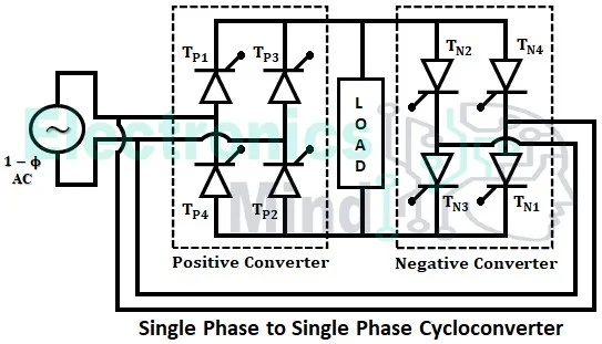
The below shows the circuit of single-phase to single-phase bridge-type configuration step down cycloconverter.
This type of cycloconverter circuit employs two single-phase fully-controlled converters known as positive and negative converters. These two converters are connected in antiparallel. The positive converter supplies load current when the output undergoes the first positive half cycle. Whereas, in the negative half of the output cycle negative converter supplies the load current.
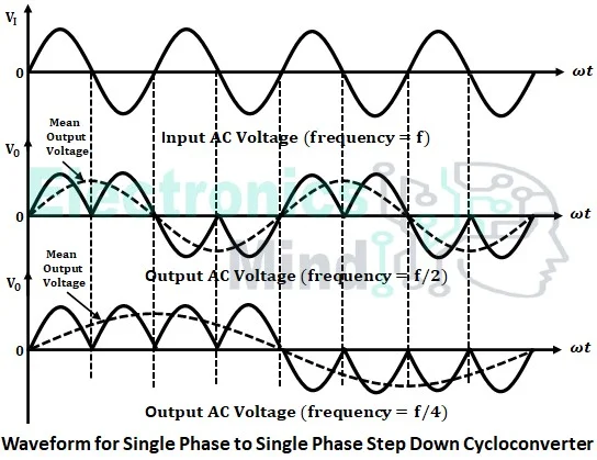
It should ensure that two converter circuits should not be in conduction at the same time, otherwise a short circuit will take place at the input terminals. The below output voltage waveform shows the converter operation when the input frequency is reduced to ½ and ¼ at the output terminals.
Three-Phase to Single Phase Cycloconverters :
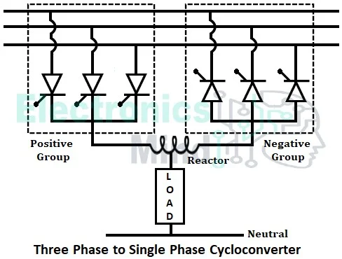
When there is a need for output voltage waveform vary nearly to sinusoidal wave, three-phase to single-phase cycloconverters are best suited. Since single-phase to single-phase cycloconverters can supply non-sinusoidal output voltage, a pure sinusoidal output voltage can be fabricated from a three-phase supply using three-phase to single-phase cycloconverters. The below shows the basic circuit configuration of a three-phase to single-phase cycloconverter.
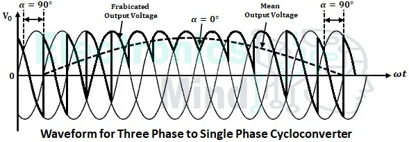
The circuit incorporates two three-phase half-wave converters with antiparallel connections. One half-wave converter circuit forms the positive group that conducts for positive load currents, while the other half-wave converter circuit forms the negative group that conducts for negative load currents. The below waveform shows the single-phase output voltage positive half-cycle fabricated from the three-phase input voltage.
Three Phase to Three Phase Cycloconverters :
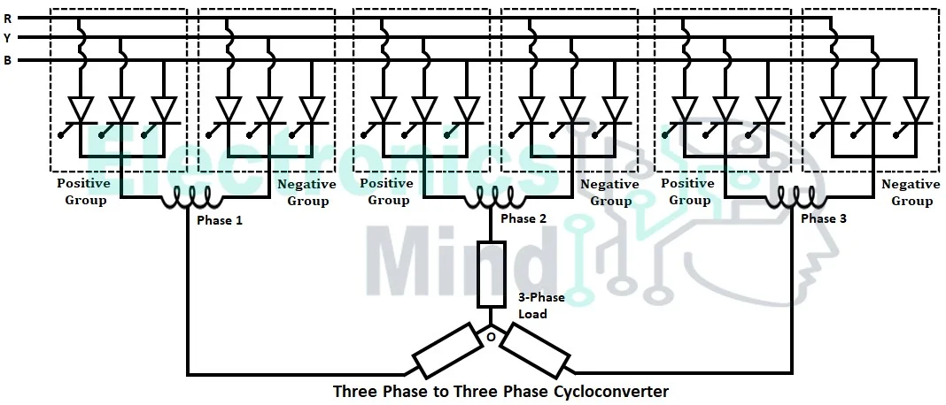
The circuit consists of two groups of thyristors per phase namely, the positive group and the negative group. The positive group produces positive switchings and the negative group produces negative switchings. Each group consists of three thyristors, thus involving a total of six thyristors per phase, which means a total of 18 thyristors are needed for the whole circuit as shown below.
This cycloconverter is also known as a three pulse three-phase to three-phase cycloconverter. The firing arrangements for thyristors for phase groups 2 and 3 lag by 120° and 240° respectively as that of group 1. By varying the firing angle, the average output voltage obtained is varied and by varying the firing sequence of the thyristors, the frequency of the output voltage can be varied.

very educative information here . am very well pleased