The class-B commutation of the thyristor is also called Resonant Pulse Commutation. It is a type of forced commutation technique that uses a charged capacitor to create a reverse current through the thyristor. So the net current flowing through it will become zero and it gets turned OFF.
In the forced commutation technique, external components (usually inductor and capacitor) are used to turn OFF the thyristor conducting load current. The thyristor can be turned-OFF either by reducing the forward current to zero by applying a large external pulse of reverse current greater than the load current (known as current commutation) or by applying a large reverse voltage (known as voltage commutation).
The class-B or resonant pulse commutation uses the current commutation technique. Hence, the class-B commutation is also known as the Current Commutation. Let us see the circuit design and working of class-B commutation of the thyristor.
Class-B or Resonant Pulse Commutation of Thyristor :
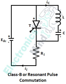
The below shows the circuit for class-B commutation or resonant pulse commutation of SCR or thyristor. The circuit incorporates a thyristor and LC resonating circuit connected in parallel with the thyristor.
Working of Class-B or Resonant Pulse Commutation :
Let us see the working of class-B commutation in four modes of operation.
Mode-1 :
Initially, when the supply is given to the circuit from source Edc, capacitor C gets charged with the polarities as shown in the figure above. The capacitor continues to charge to a voltage equal to slightly greater than the input voltage Edc. Till now the thyristor T will be in the OFF state. The path of the charging current of the capacitor is given as,
Mode-2 :
Now, at ωt = to, thyristor T is triggered and it starts conducting due to which the load current starts flowing through the load Rl and the path of the load current is given by,
But at this instant, there is one more current flowing, i.e., in the LC circuit, which is known as the resonating current iC. The resonating current is due to the discharging of the capacitor. The resonating current flows through the path.
Mode-3 :
Now at ωt = t1, after the complete discharge of the capacitor, the polarities of the capacitor get reversed with respect to the polarities shown in the above figure. Because of this, a reverse voltage of capacitor C will appear across the thyristor T. There is a resonating current developed, which is now in the reverse direction and this resonating current flows through the path,
Mode-4 :
In the previous case, i.e., ωt = to, the resonating current was flowing in the same direction as that of load current. But the reverse resonating current flows in the direction opposite to load current, since thyristor is a unidirectional device, the net current will be iT = il – iC.
Whenever the thyristor current reduces to a current below its holding current, it turns OFF. This is the reason why the thyristor commutating resonant current class-B commutation is also known as resonant pulse commutation.
After the commutation of thyristor, T capacitor C will again charge to voltage slightly greater than the input voltage Edc. Again, when the thyristor T is triggered at the next instant, the same process continues. Here we can notice that, after triggering the thyristor T, it is commutated by itself. Therefore, class-B commutation is also called Self-commutation.
Waveform of Class-B or Resonant Pulse Commutation :
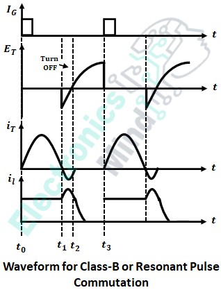
The below shows the waveform of class-B or resonant pulse commutation.
In the above waveform, IG represents the thyristor gate triggering pules, ET and iT are the voltage drop and current flow of the thyristor respectively and il is the load current.
We can see that when a triggering pulse is applied to the gate terminal of the thyristor, it turns-ON, and thyristor current iT flows through it while supplying the load current il. At the same time, the capacitor discharges through the thyristor as seen in mode-2. Now when the capacitor completely discharges, the capacitor polarity will be reversed and thus a negative voltage is applied to the thyristor which is at time t1 as seen in mode-3.
The capacitor starts discharging with reverse polarity, and at an instant when iC becomes higher than the iL. The thyristor gets turned-OFF which is represented from time t1 to t2, due to this the load current decreases and becomes zero after t2. Once the thyristor gets OFF, the supply voltage will appear across the thyristor. Again when the gate pulse is applied the thyristor starts conducting and the same process continues.
Design of Class-B Commutation Circuit :
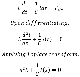
Applying KVL to the LC circuit loop, we get,
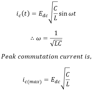
By solving the above equation, the instantaneous value of the increasing resonant current is given by,
In this commutation method, the thyristor takes a time approximately equal to the one-quarter period of the resonant circuit to reverse bias. Hence, the turn-oFF time of the thyristor is given by,
Morgan’s chopper employs the class-B commutation where the inductor L is replaced by a saturable reactor which helps to prevent the commutation failure; thus, successful commutation is achieved. One of the main advantages of the class-B commutation circuit is that the turn-ON and turn-OFF times of the thyristor can be adjusted to our requirement, by selecting proper commutating components.


