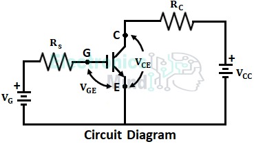
The insulated gate bipolar transistor (IGBT) is a semiconductor device developed with combined characteristics of MOSFET and BJT. It has emitter-collector characteristics as BJT and control features of MOSFET. IGBTs have high OFF-state and low ON-state voltage characteristics of BJT and high input impedance characteristics of MOSFET. In this article let us see the characteristics of IGBT.
Static V-I Characteristics of IGBT :
The steady-state V-I characteristics of n-channel IGBT are shown below. The V-I characteristics of IGBT are plotted between output or collector current IC and collector-emitter VCE for different values of gate-to-emitter voltage VGE.
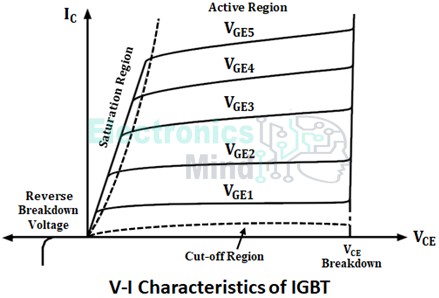
The IGBT is turned ON when the gate voltage applied is greater than the threshold value and can be turned OFF by reducing gate voltage below the threshold value. The output current IC will increase with an increase in voltage VGE. The VCE breakdown is the forward breakdown voltage above which the current and voltage through the device will high resulting in huge power dissipation.
Transfer Characteristics of IGBT :
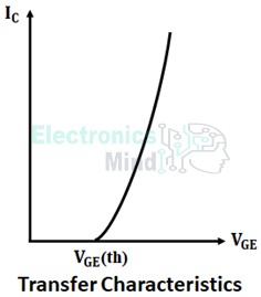
The transfer characteristics of IGBT are drawn between output collector current IC and gate-emitter voltage VGE as shown below. These characteristics are similar to a power MOSFET that IGBT will start conducting only when applied VGE is greater than threshold value VGE(th).
Switching Characteristics of IGBT :
The below shows the switching characteristics of IGBT. A positive voltage is applied across the gate-emitter terminals to turn IGBT. When gate voltage becomes more than the threshold value, the collector current IC starts flowing and the collector-emitter voltage VCE starts falling.
The delay by gate-emitter voltage VGE to reach the threshold value and IC starts increasing is known as a turn-ON delay (td(on)). The rise time (tr) is defined as the time in which collector current IC reaches its full value and collector-emitter voltage VCE falls to the minimum value. The turn ON time of IGBT is,
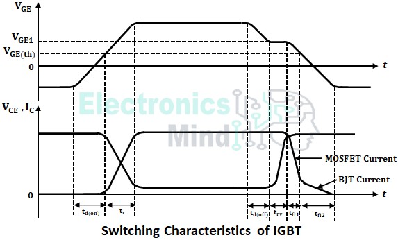
In order to turn OFF the MOSFET, the gate voltage is reduced. When the gate-emitter voltage reaches the value equal to VGE1 (voltage at which IGBT comes out saturation), VCE starts increasing. The time taken to reduce the voltage to VGE1 is known as turn-OFF delay td(off).
When VCE reaches supply voltage, collector current IC starts reducing at a rapid rate and falls until gate voltage VGE reaches to threshold value VGE(th). This rapid decrease in collector current is basically due to internal MOSFET. The VGE goes to zero and becomes negative.
Even after gate voltage reaches zero, collector current IC flows for a while. This flow of collector current is due to stored carriers and it is internal BJT current. Thus the turn-OFF time of IGBT is higher than MOSFET and is given as,
Where
- trv = Voltage rise time
- tfi1 = MOSFET current fall time
- tfi2 = BJT current fall time.
A voltage in the range of +10V to +15V is usually applied to the gate to turn ON an IGBT and can be turned OFF by bringing the gate voltage to zero value. Some of the advantages of IGBT are low ON-state voltage drop, simple gate drive, low switching losses, etc. Though IGBTs are more expensive than BJT, their advantages make them favored in many applications.