What is Buck Converter?
A buck converter is a dc-to-dc step-down converter or step-down chopper that lower the magnitude of the applied dc input signal at the output side. Basically, a buck converter is similar to a step-down transformer that converts the applied dc input signal to the desired value at the output side which is less than the input signal.
Generally in electronic circuits, there is a requirement for a wide variety of regulated dc power supplies. The chopper circuits are the simple and most efficient way to obtain desired dc supply from a fixed or non-regulated dc supply. The regulation of dc supply is achieved by switching devices normally a power transistor (BJT, MOSFET, or IGBT) and an LC filter is connected to the switch to reduce current and voltage ripples.
Circuit Diagram of Buck Converter :
The circuit configuration of the buck converter is shown in the below figure. It consists of a power semiconductor device (e.g. MOSFET, IGBT, BJT, etc.) that acts as the switch. Along with the semiconductor device, a diode is connected across the load which also acts as the switch.
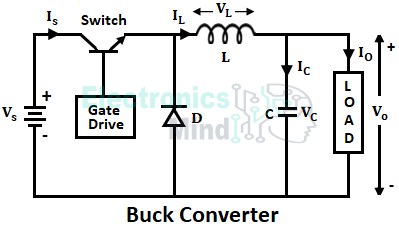
The two switches are connected to the load through a low-pass LC filter in order to reduce current or voltage ripples. The inductor is connected in series with the load which stores energy during the ON period of the switch.
The switch (power transistor) which connects and disconnects the load to get desired output is controlled by using Pulse Width Modulation(PWM). The dc-to-dc converters normally use a time-based PWM control signal that provides a duty cycle by which accurate and desired output voltage is obtained.
Operation of Buck Converter :
By using a buck converter the output voltage can be controlled from zero to the input voltage level. The operation of a buck converter is divided into two modes.
When Switch is ON :
In mode-I, the switch is closed at t = 0. When the switch is turned ON diode becomes reverse biased and thus it will be in the non-conducting state. The supply current starts flowing through filter components inductor (L) and capacitor (C), and through the load, as shown below.
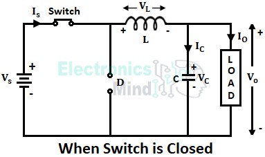
Now when the switch has closed the inductor in the current flow path stores energy and the capacitor stores the charge. The voltage across the capacitor will appear across the load. On applying KVL to the above circuit, the voltage across the inductor will be the difference of the supply voltage (VS) and output voltage (VO).
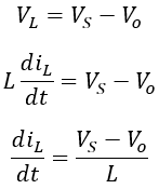
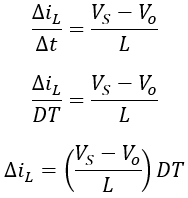
We know that the duty cycle is written as,
During the ON period of the switch, TON = DT thus Δt = DT. Therefore, the above equation can be written as,
When Switch is OFF :
The mode-II starts when the switch is opened, in this condition the supply is disconnected from the load and the inductor will start acting as the source.
The stored energy by the inductor in the previous mode will start releasing with reversed polarity due to which the diode gets forward-biased and the inductor current flows through the capacitor, load, and diode as shown below.
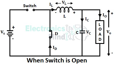
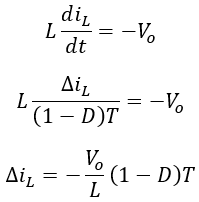
The current will continue to flow through the load till the current in the inductor falls to zero value. Once the inductor is discharged completely, the diode gets reverse bias and the switch is closed again thereby repeating the cycle. On applying KVL to the above circuit,
We know that,
Substituting above Δt in equation 1, we get,
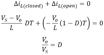
The above equation gives the rate of change in current through the inductor when the switch is open. The net change of current through the inductor in one cycle of supply will be zero. Thus,
The below shows the waveforms of voltage and current for two modes of operation.
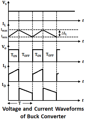
If suppose the switch is closed again before the inductor current reaches zero then a continuous load current operation is obtained. If the switch is closed after complete discharge of the inductor then the load current will be discontinuous.
By changing the switching frequency, the voltage regulation is controlled. If TOFF is increased the average output voltage is lowered, if TOFF is decreased, the average output voltage is increased.
Since the output voltage obtained is less than the input voltage the circuit is called a step-down converter. Due to the requirement of only one semiconductor device, buck converters are very simple and highly efficient. The applications of buck converters are dc motor speed control and regulated dc power supplies.