What is Buck-Boost Converter?
A buck-boost converter is a combination of a buck converter and a boost converter i.e., it is a cascade combination of a buck converter circuit and a boost converter circuit. A buck-boost converter is a dc-to-dc converter by which we can obtain an output voltage greater or lesser than the input voltage. The polarity of the output voltage is opposite to that of the input voltage.
In the last two articles, we have seen about buck and boost converter. We know that a buck converter is a step-down chopper that gives output voltage below the input voltage. Whereas a boost converter is a step-up chopper that gives output voltage greater than the input voltage. A buck-boost converter circuit is formed by utilizing the strong points of this both converters.
Construction of Buck-Boost Converter :
The circuit diagram of a typical buck-boost converter is shown in the below figure. The circuit consists of a solid-state device (power MOSFET is used in this converter) connected in series with the supply source similar to a buck converter.
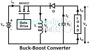
An inductor will be connected in parallel with the output terminals and a diode is connected similarly to that as seen in the boost converter. The solid-state device which is basically a semiconductor device will act as the switching device.
The switching device is turned ON and OFF by controlling the gate terminal using Pulse Width Modulation(PWM). The circuit will operate as the step-down or step-up chopper by controlling the duty cycle thus obtaining an output more or less than the input supply.
Working of Buck-Boost Converter :
When the switch (MOSFET) is turned ON, the supply current starts flowing through the switch, inductor, and back to the supply as shown below. The diode (D) will be reverse biased and acts as the open switch due to which load will be isolated from the supply current.
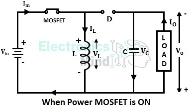
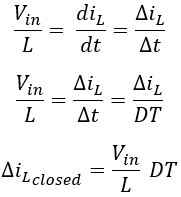
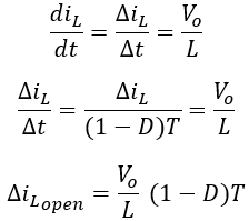
The supply source will provide energy to the inductor and the inductor will start charging with the polarity shown above. No energy is supplied to the load by the supply source during this interval. During the ON period of the switch, the current through the inductor can be given by applying KVL to the above circuit.
We know that duty cycle D = TON/T since the switch is closed for period TON = DT, we can say that dt = DT.
When the switch is turned OFF, the decrease in inductor current generates a negative voltage across the inductor i.e., with reverse polarity. Now the stored energy is large enough to forward bias the diode, and this energy in the inductor will be transferred to the load.
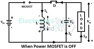
The current which was flowing through the switch and inductor in the previous interval will now flow through the inductor, capacitor, load, diode and back to the inductor as shown above. The inductor will go on discharging and the inductor current will fall until the MOSFET is switched ON again in the next cycle. During the OFF period of the switch, the current through the inductor can be given using KVL,
The turn-OFF period of the switch is given as, TOFF = T – TON = T – DT = (1 – D)T, thus we can say that dt = (1 – D)T.
From the above operation, we have seen that when the switch is ON inductor will be charged and when the switch is OFF inductor will be discharged. Therefore the net change in inductor current over any one complete cycle is zero.
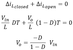
Therefore, from the above equation output voltage will depend upon the duty cycle. If duty cycle (D) is below 0.5, the circuit will operate as the buck converter or step-down dc-to-dc converter i.e., the output will be smaller than the input. If duty cycle (D) is above 0.5, the circuit will operate as the boost converter or step-up dc-to-dc converter i.e., the output will be greater than the input.
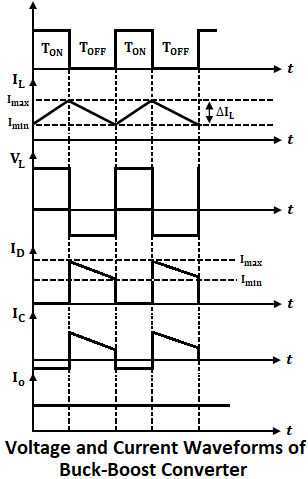
Both input and output current is discontinuous, but inductor current can be continuous or discontinuous and output voltage remains constant due to the large value of the capacitor. The below shows the waveforms for voltage and current of the buck-boost converter.
Applications of Buck-Boost Converter :
- Battery-powered systems.
- It is used in self-regulating power supplies.
- In power amplifiers.
- Consumer electronics.